

Gutter and Siding Protection Device and System
a protection device and gutter technology, applied in the field of new gutter protection system, can solve the problems of not currently having a gutter protection system to protect gutters, potentially building siding and landscape plants, and gutters and landscape plants are prone to being damaged during re-roofing activities, so as to reduce incidental damage to gutters, economic benefits, and the effect of reducing the likelihood of gutter damag
- Summary
- Abstract
- Description
- Claims
- Application Information
AI Technical Summary
Benefits of technology
Problems solved by technology
Method used
Image

Examples
example 1
Describing FIGS. 1-3 and 13
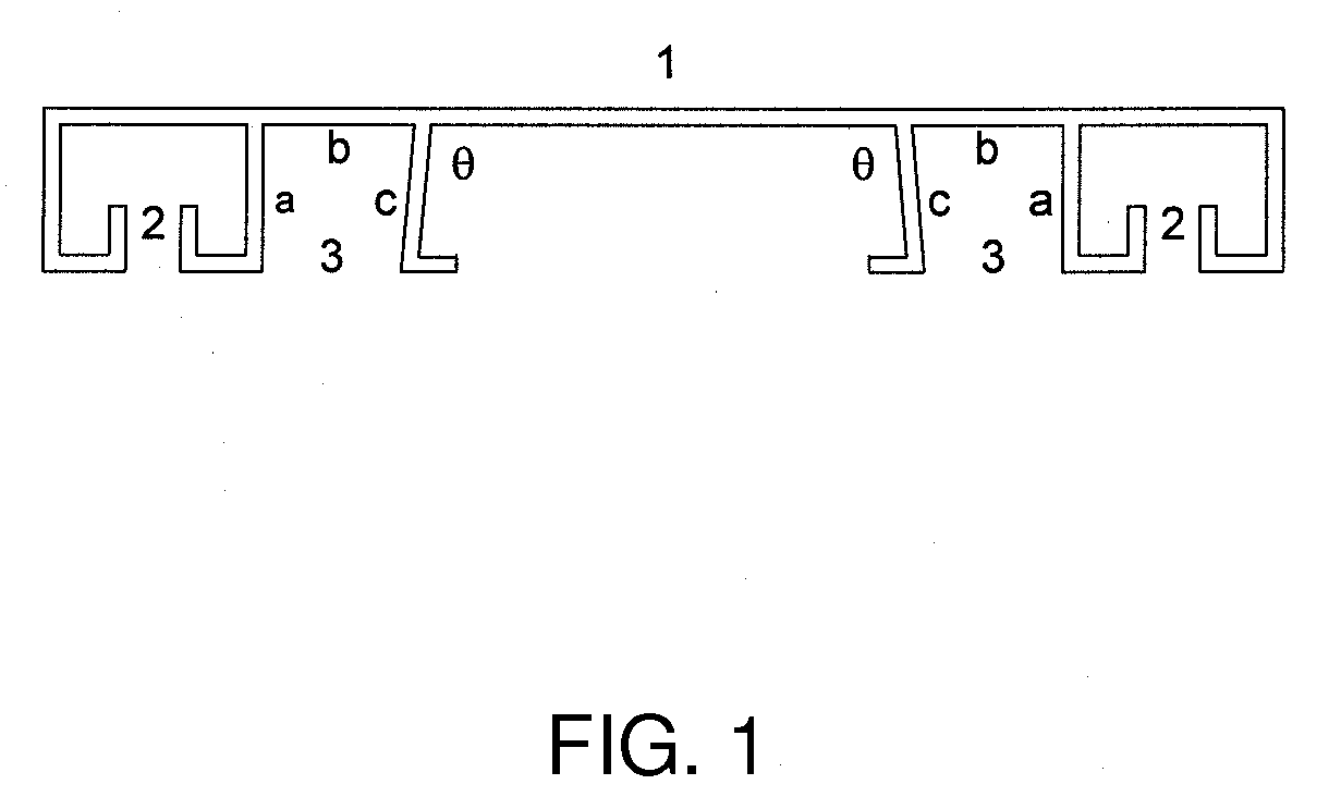
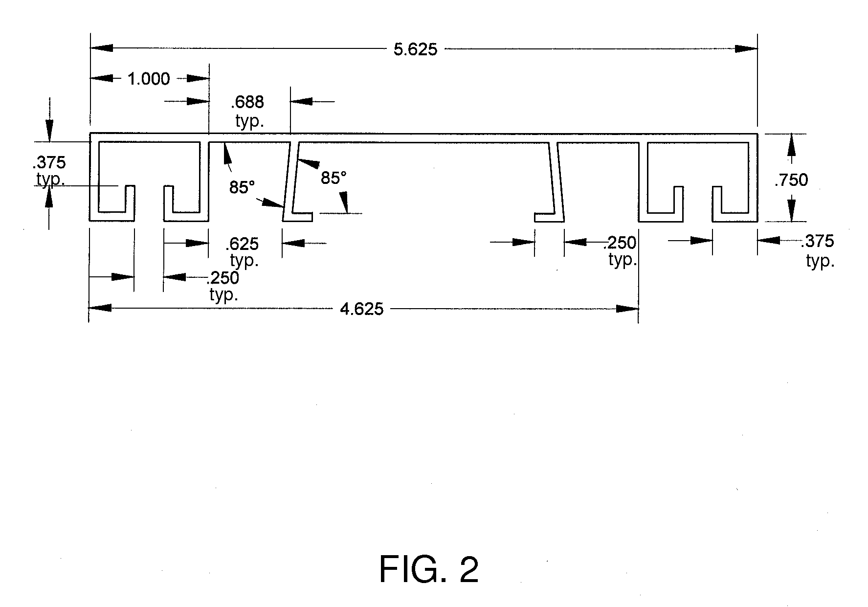
[0041]One embodiment of a gutter protection plate is illustrated in FIG. 1. In this embodiment, the top plate comprises a top panel 1, a gutter securing means 2, and a curtain hanging means 3 (with T-shaped hanging bracket shown in FIG. 6C and FIG. 9). Exemplary dimensions are shown in FIG. 2. The width of the top plate is sized to cover the gutter (gutter trough and gutter front wall and lip) when the gutter is mounted on a structure. The width of the top plate is further sized such that when the securing means, such as an inverted U-shaped channel 3, is positioned on the lip of a gutter front wall, the top plate covers or mostly covers the gutter trough. In one embodiment, the top surface of the top panel 1 is flat and smooth. A smooth top surface more easily allows debris to slide over or off the top plate. If ridges are added for strength, they are preferable aligned perpendicular to the length of the top plate (perpendicular to the roof line or gutter...
example 2
Describing FIGS. 4-7
[0048]Various top plate shapes within the scope of the invention are readily envisioned. FIG. 4 illustrates and alternative embodiment of the bracket described in example 1. In this embodiment, the inside and outside edges of the top plate are rounded and a central section is made from thicker, solid material. The top plate illustrated in FIGS. 1 and 2 is symmetrical.
[0049]FIG. 5 illustrates that the top plate can be flat A, convex B, or concave C. The figure shows a cross-section of the top plate. The degree of curvature or particular slope is not limited to that shown in the FIG. 5. Each of the top plates shown in FIG. 5 contains an outside edge overhang, but not a curtain hanging means, beyond the inverted U-shaped channel gutter securing means. However, the invention is not limited to the presence or absence, or shape or size of an overhang. The top plates shown in FIG. 5 further illustrate non-symmetrical top plates, with singled inverted U-shaped channels f...
example 3
T-shaped Curtain Hanging Means FIGS. 8-10
[0053]In one embodiment, a T-shaped curtain hanging bracket (FIG. 8) comprises a first top hook a, a first shaft section b that connects the first hook a to a loop section c, and a second shaft section d that connects the loop section c to a second hook e. The first shaft section b runs roughly parallel to the second shaft second d. The hooks a, e are sized to enable them to be inserted into a T-slot of the top plate. The bracket is inserted into the T-slot with the hooks running parallel to the slot, the bracket is then twisted about 90°. The T-shaped bracket is then lowered such that the hooks engage the inner, vertically oriented walls of the T-slot. See FIG. 9.
[0054]A T-shaped bracket can have a number of configurations that are compatible with the invention, as illustrated in FIG. 10. For instance, the T-shaped bracket can have a loop A, hook, B, or snap C.
PUM
 Abstract
Description
Claims
Application Information