
Double oven combination with an integrated cooling air and exhaust air flow arrangement

a technology of exhaust air flow and integrated cooling air, which is applied in the direction of domestic stoves or ranges, furnaces, heating types, etc., can solve the problem of sensitive wood

Active Publication Date: 2008-08-07
BSH HOME APPLIANCES CORP
View PDF6 Cites 26 Cited by
  • Summary
  • Abstract
  • Description
  • Claims
  • Application Information

AI Technical Summary

Benefits of technology

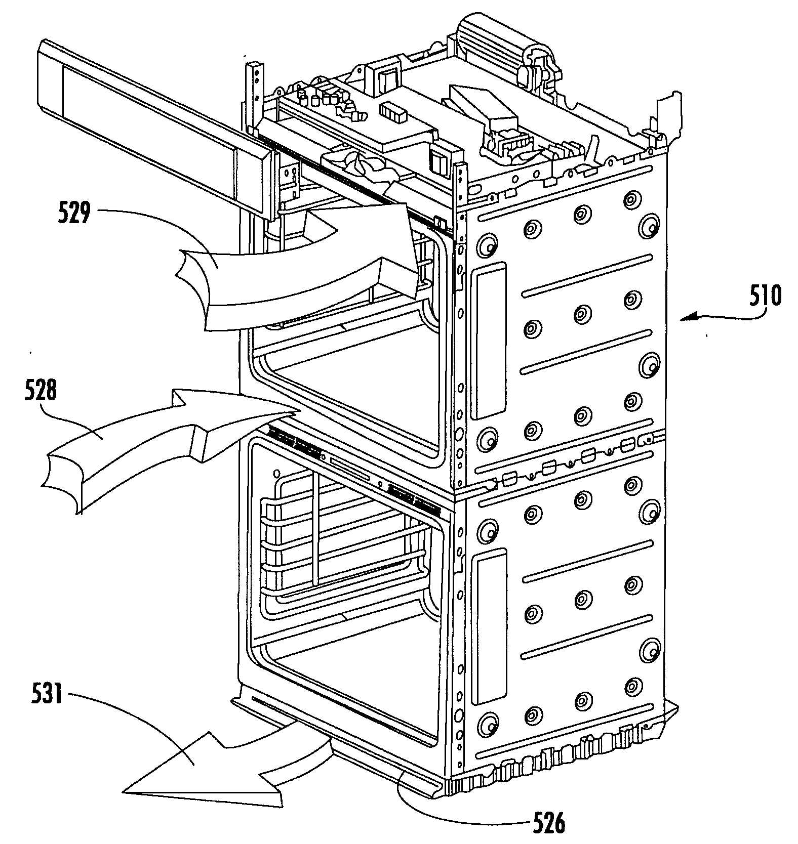
[0010]In accordance with yet further details of the one aspect of the present invention, the latch plate shield is cooperatively configured with respect to the top portion of the oven door of the lower oven for influencing heated air exiting the top portion of the oven door to enter the mid-channel of the second air guiding path and latch plate shield assembly including at least one cooling air aperture for the entry of cooling air into the mid-channel of the second air guiding path, whereby the integrated cooling air and exhaust air flow arrangement efficiently guides exhaust air away from the upper oven and the lower oven while at the same time effectively flowing cooling air relative to the double oven combination to promote desired cooling of the double oven combination.

Problems solved by technology

U.S. Pat. No. 5,957,557 further describes other perhaps detrimental aspects of such built-in units, including the fact that wood is sensitive to dampness and the effects of heat and the requirement to provide each appliance with its own power supply, often requiring installation to be carried out by a specialist electrician.
Moreover, U.S. Pat. No. 5,957,557 notes that the electrical appliances of such built-in units are generally not stackable for static reasons.

Method used


Image

  • Double oven combination with an integrated cooling air and exhaust air flow arrangement
  • Double oven combination with an integrated cooling air and exhaust air flow arrangement
  • Double oven combination with an integrated cooling air and exhaust air flow arrangement

Examples


Embodiment Construction

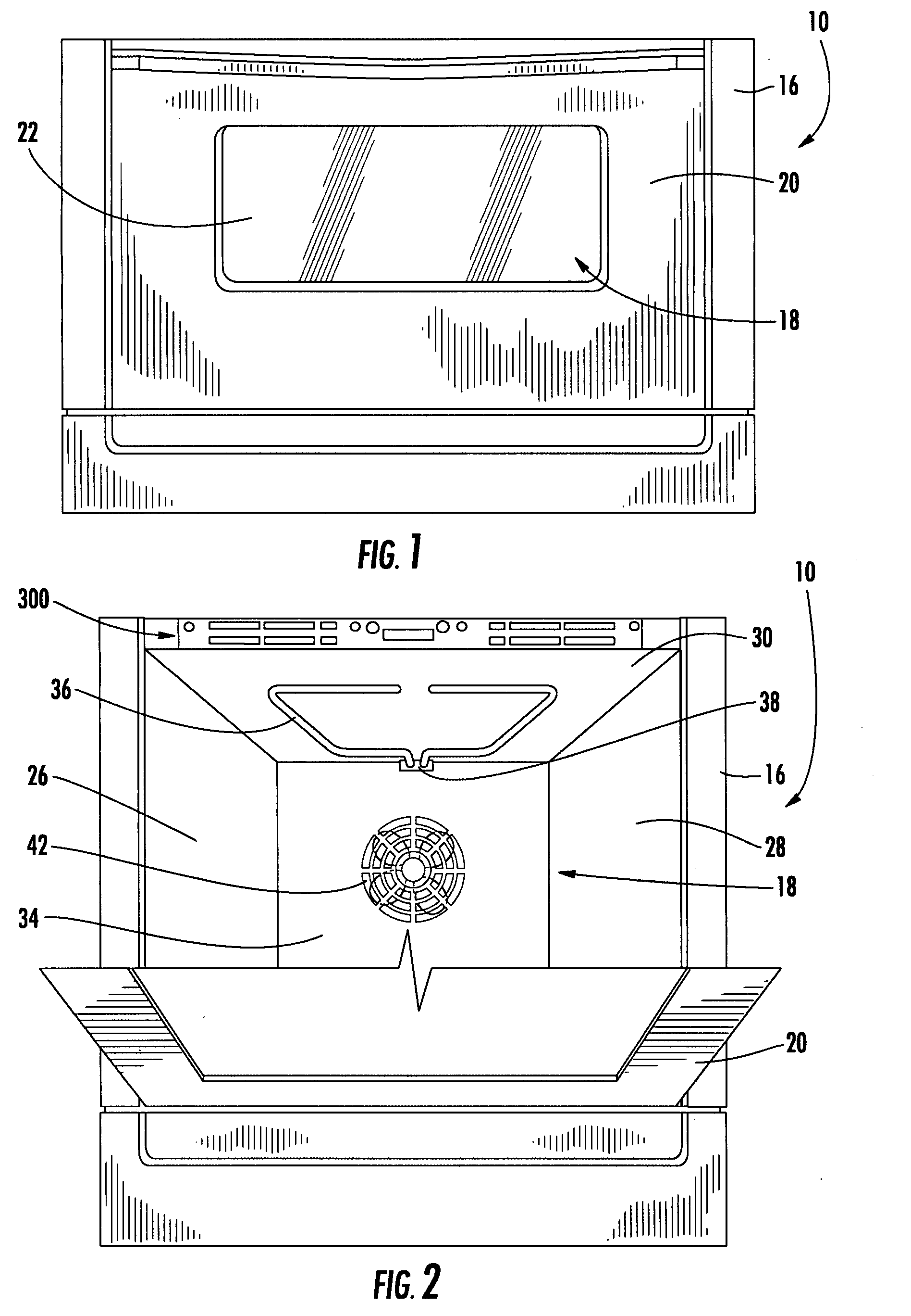
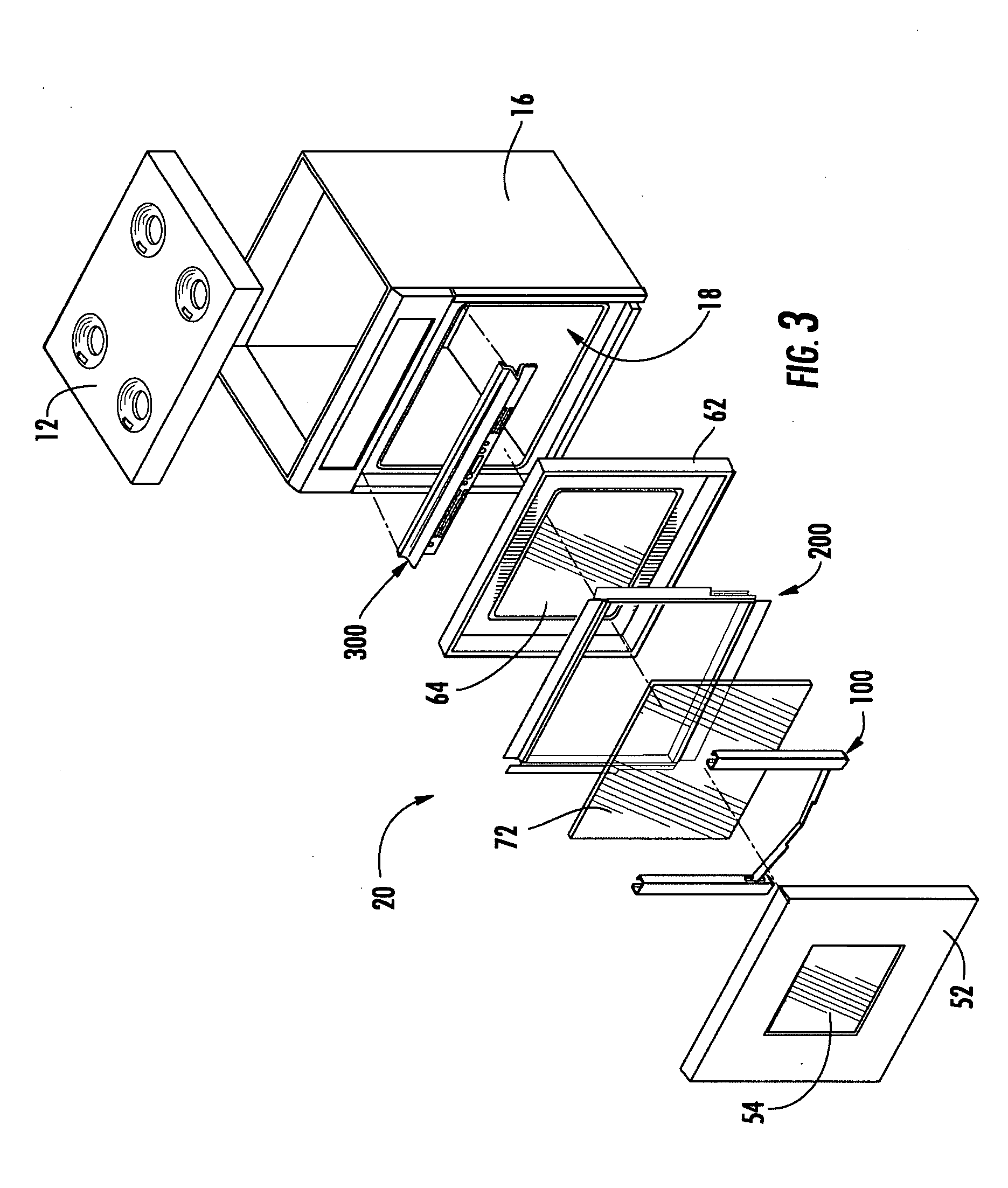
[0027]Referring now to FIGS. 1 and 2, an electric or gas oven or range 10 (“oven” is used for ease of reference hereinafter) is operable to cook and heat foodstuffs and other substances. Two units of the oven 10 can be arranged relative to one another to form a double oven combination and, additionally, such a double oven combination can be configured to be “built-in” double oven that is installed in a recessed manner in, for example, an area of a household—in other words, permanently secured relative to the household area and integrated with other elements of the household area to provide a consistent decorative appearance. Such a double oven combination may be comprised of two ovens each of which is a unit configured identically to the oven 10 described hereinabove with one of these ovens being an upper oven disposed at a predetermined spacing above the other oven (the lower oven) and can include an associated single control panel for controlling the operation of both the upper an...


PUM


Abstract

A double oven combination is configured to be “built-in” an area of a household—in other words, permanently secured relative to the household area and integrated with other elements of the household area to provide a consistent decorative appearance. The double oven combination comprises an upper oven and a lower oven each of which may be a convection or non-convection oven that cooks and heats food and other substances via radiant and convective heating, and a control panel. The double oven combination has an integrated cooling air and exhaust air flow arrangement for efficiently guiding exhaust air away from the upper oven and the lower oven while at the same time effectively flowing cooling air relative to the double oven combination to promote desired cooling of the double oven combination.

Description

BACKGROUND OF THE INVENTION[0001]The invention disclosed herein relates generally to an integrated cooling air and exhaust air flow arrangement for influencing the heat dissipation of a double oven combination, and more particularly to an integrated cooling air and exhaust air flow arrangement having a cooling air only guiding path for guiding cooling air downwardly to a base channel extending below the lower oven of the double oven combination.[0002]Cooking appliances have been available, for example, in configurations known as built-in wall ovens and one type of built in oven that is commercially available is a double oven which features two independently operable convection or non-convection ovens. Such double ovens can be installed in a kitchen of a home residence, another room of a home residence, or in other settings in a manner such that one of the pair of ovens is located above the other of the pair of ovens. Moreover, one commercially available configuration of a double ove...

Claims


Application Information

Patent Timeline
IPC IPC(8): A21B1/26
CPCF24C15/006
Inventor ELKASEVIC, SUADMAY, GEORGEPENUEL, MIKESHERBERT, KEVIN W.
Owner BSH HOME APPLIANCES CORP
Learn More