Encoder
a technology of encoders and encoders, applied in the field of encoders, can solve the problems of reducing the light amount of illumination lights that contribute to interference and the light amount of interference light, and achieve the effect of improving the efficiency of illumination lights
- Summary
- Abstract
- Description
- Claims
- Application Information
AI Technical Summary
Benefits of technology
Problems solved by technology
Method used
Image
Examples
modified example 1
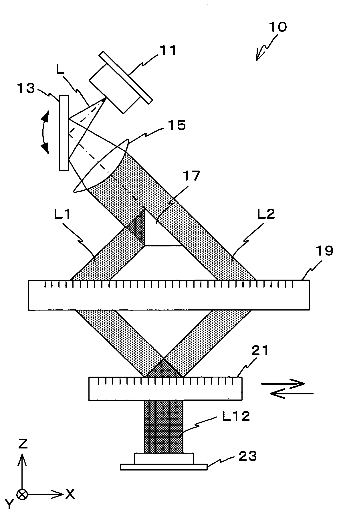
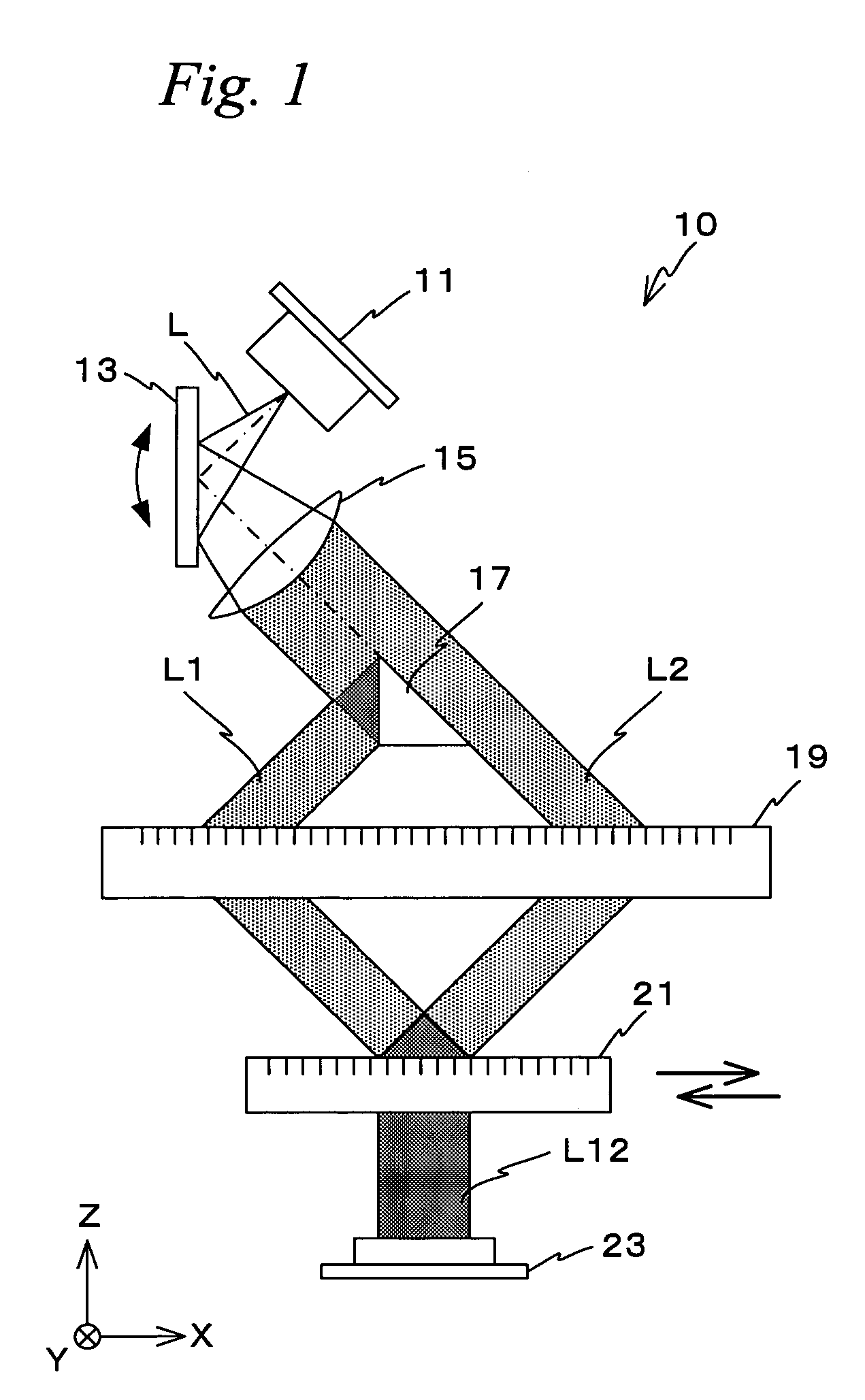
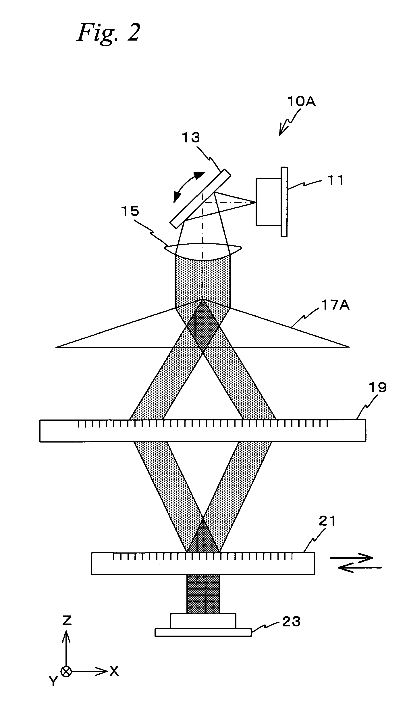
[0029]FIG. 2 is a view showing an encoder 10A related to a modified example 1. Encoder 10A has a prism 17A whose vertex angle is obtuse instead of triangle prism 17 having surfaces that are orthogonal to each other, which is a different point from encoder 10. In encoder 10A, prism 17A is placed so that two surfaces with the vertex angle in between are located within a projection plane of an illumination light modulated by scan mirror 13, and after an illumination light is spatially split into two illumination lights by prism 17A, the illumination lights are made to be incident on the same position on the upper surface of movable scale 21 by diffraction grating for deflection 19. In encoder 10A, the projection plane of each illumination light that is formed on diffraction grating for deflection 19 has a semicircular shape that is symmetric to the Y-axis, but since the illumination lights are incident on the same position on the upper surface of movable scale 21, it becomes possible t...
modified example 2
[0030]FIG. 3 is a view showing an encoder 10B related to a modified example 2. In encoder 10B, the function of prism 17A that is used in encoder 10A related to the modified example 1 described above is realized by combining a pair of prisms 17B. As is shown in FIG. 3, in encoder 10B, a pair of prisms 17B are placed so that the inclined surfaces of prisms 17B face each other. After an illumination light is spatially split into two illumination lights by a pair of prisms 17B, the illumination lights are made to be incident on the same position on the upper surface of movable scale 21 by diffraction grating for deflection 19. Accordingly, it becomes possible to minimize wasted illumination lights that do not contribute to the interference and to improve the use efficiency of illumination lights in encoder 10B.
[0031]Incidentally, a pair of prisms 17B are used in this modified example, but a pair of prisms 17B may be integrally molded by, for example, glass mold press, injection molding,...
modified example 3
[0032]FIG. 4 is a view showing an encoder 10C related to a modified example 3. In encoder 10C, the function of prism 17A used in encoder 1A related to the modified example 1 described above is realized by combining a pair of blazed diffraction gratings 17C. As is shown in FIG. 4, in encoder 10C, a pair of blazed diffraction gratings 17C are placed so that both of them are located within a projection plane of an illumination light. An illumination light incident on blazed diffraction grating 17C on the −X side is diffracted in a left-oblique-downward direction, and an illumination light incident on blazed diffraction grating 17C on the +X side is diffracted in a right-oblique-downward direction. Illumination lights that have been spatially split by a pair of blazed diffraction gratings 17C as is described above are made to be severally incident on the same position on the upper surface of movable scale 21 by diffraction grating for deflection 19. Accordingly, it becomes possible to m...
PUM
 Abstract
Description
Claims
Application Information
 - R&D
- Intellectual Property
- Life Sciences
- Materials
- Tech Scout
- Unparalleled Data Quality
- Higher Quality Content
- 60% Fewer Hallucinations
Browse by: Latest US Patents, China's latest patents, Technical Efficacy Thesaurus, Application Domain, Technology Topic, Popular Technical Reports.
© 2025 PatSnap. All rights reserved.Legal|Privacy policy|Modern Slavery Act Transparency Statement|Sitemap|About US| Contact US: help@patsnap.com


