Circuit for matching the load impedance of an electronic device

a technology of load impedance and electronic device, which is applied in the direction of waveguide type devices, electrical equipment, multiple-port networks, etc., can solve the problems of inability to use lc networks in systems with very broad bands, inability to conduct large quantities of current, and complex circuits for monitoring impedance and sophisticated control strategies

Inactive Publication Date: 2008-08-07
TELEFON AB LM ERICSSON (PUBL)
View PDF4 Cites 30 Cited by
  • Summary
  • Abstract
  • Description
  • Claims
  • Application Information

AI Technical Summary

Benefits of technology

[0011]The third problem depends on the need to know the module and phase of the load impedance exactly, w

Problems solved by technology

Nevertheless, they are affected by different types of problem such as the dimension of the corrector and the cost thereof, frequency sensibility, the complexity of load impedance detection and of control strategy.
The first problem is due to the need to create numerous modulated high impedance inductances, to working frequencies and to the need to conduct great quantities of current if the application is power amplification.
The second problem depends on the correction strategy, which is based on us

Method used


Image

  • Circuit for matching the load impedance of an electronic device
  • Circuit for matching the load impedance of an electronic device
  • Circuit for matching the load impedance of an electronic device

Examples


Embodiment Construction

[0022]The performance of a device in mismatched condition has an impact that depends on the mismatch level. This is expressed by the standing wave ratio or VSWR. In mobile radio applications transmitting a VSWR up to 6:1 is normally required to be guaranteed, whilst in each case the supply current received by the active circuits to the battery should not exceed set limits. Providing high amplification linearity enables one to maintain communication active, specially for high bit-rate communications.

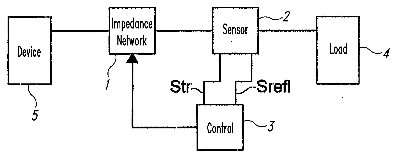
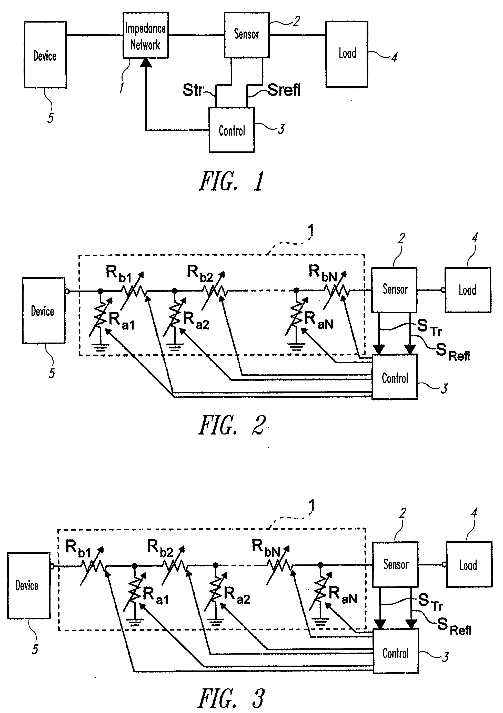
[0023]In FIG. 1 there is shown a device for matching load impedance according to one embodiment. Said device comprises a mismatching corrector 1, in particular of resistive type, a mismatching sensor 2 and a control circuit 3. The mismatching sensor 2 is of known type, is coupled with the network 1 and with the load 4, is suitable for measuring the ratio between the stationary incident and reflected standing waves in transferring power from the electronic device 5 to the load 4; and is su...


PUM


Abstract

A circuit matches the load impedance of an electronic device. The circuit comprises an impedance network, a control circuit suitable for varying the impedance of said network and a sensor coupled with said network and said load and suitable for detecting the ratio between the incident and reflected standing waves in transferring power from the electronic device to the load; the sensor is suitable for providing two signals substantially proportional to the incident and reflected amplitude of the waves at the control circuit. The impedance network is a network of variable resistances and the control circuit is suitable for varying the value of the resistances to lower said ratio between the incident and reflected standing waves to a value that ensures the transfer of power from the electronic device to the load.

Description

BACKGROUND[0001]1. Technical Field[0002]The present invention relates to a circuit for matching the load impedance of an electronic device.[0003]2. Description of the Related Art[0004]Electronic circuits operate on a load that is suitably matched to display their nominal performance. This becomes particularly important for radio-frequency circuits, especially for power amplifiers of radio transmitters.[0005]Using impedance matchers is known in the prior art. A solution near to the needs of high-integration radio-frequency systems is known from U.S. Pat. No. 379,494. Said patent discloses an antenna tuner of automatic type that comprises digital control circuits for selecting reactive tuning elements of an antenna impedance coupling network. The tuner system provides rapid transformations of impedance of a multiple antenna to the load resistance to effectively transfer the power of a power amplifier of a portable radio transmitter to each antenna selected above a wide frequency range...

Claims


Application Information

Patent Timeline
IPC IPC(8): H03H7/38
CPCH03H7/40
Inventor SCUDERI, ANTONINOCARRARA, FRANCESCOPRESTI, CALOGERO DAVIDEPALMISANO, GIUSEPPE
Owner TELEFON AB LM ERICSSON (PUBL)
Why Eureka
Try Eureka