
Apparatus and method for base band filtering

a filter and base band technology, applied in the direction of amplitude demodulation, line-fault/interference reduction, pulse technique, etc., can solve the problems of low amplitude variation in the pass-band and high stop-band rejection, high circuit complexity, and limited interference between different users operating within the same channel. achieve the effect of reducing circuit complexity and improving performan

Active Publication Date: 2011-12-27
NOKIA TECH OY
View PDF9 Cites 0 Cited by
  • Summary
  • Abstract
  • Description
  • Claims
  • Application Information

AI Technical Summary

Benefits of technology

The present invention provides a better way to filter base band signals in wireless systems. It offers improved performance and lower circuit complexity compared to conventional methods. The invention allows for a simpler filtering process that allows for better amplitude response in the pass band while maintaining a large enough attenuation in the stop band. The invention also allows for a more flexible design and can be used in various wireless systems. The invention can be implemented using a cyclic prefix and can be used for both digital and analog filtering. Overall, the invention simplifies the filtering process and improves the performance of base band filtering in wireless systems.

Problems solved by technology

The interference between different users operating within the same channel is limited by the use of base band filters.
Since the maximum data transfer speed is correlated to the performance of the base band filters, they can become a bottleneck of the performance of the whole system and further result in high circuit complexity.
A main problem is that small amplitude ripple in pass band and typically high requirement for stop band attenuation result in the provision of a filter apparatus having a long impulse response in time domain, which means that the signal energy will be distributed in time domain so that part of the energy which is in one transmitted symbol may leak to the next symbol causing inter-symbol-interference.
High order filters result in low amplitude variation in the pass-band and high stop-band rejection, but also have a long impulse response which spreads the filtered signal energy in time domain, and further require complex circuitry.
A system with low order filtering, however, results in poor spectral efficiency, since the separation between different users in frequency domain must be increased to avoid interference.
On the other hand, long impulse responses created by high order filtering cause signal spreading in time domain, which results in inter-symbol interference or requires longer guard intervals between transmitted symbols, both of which limit the speed of the data transfer.

Method used


Image

  • Apparatus and method for base band filtering
  • Apparatus and method for base band filtering
  • Apparatus and method for base band filtering

Examples


Embodiment Construction

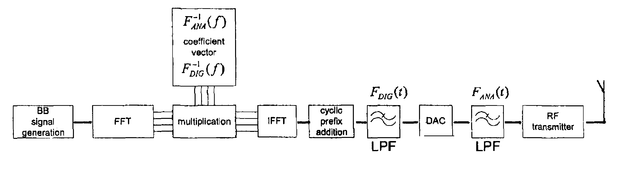
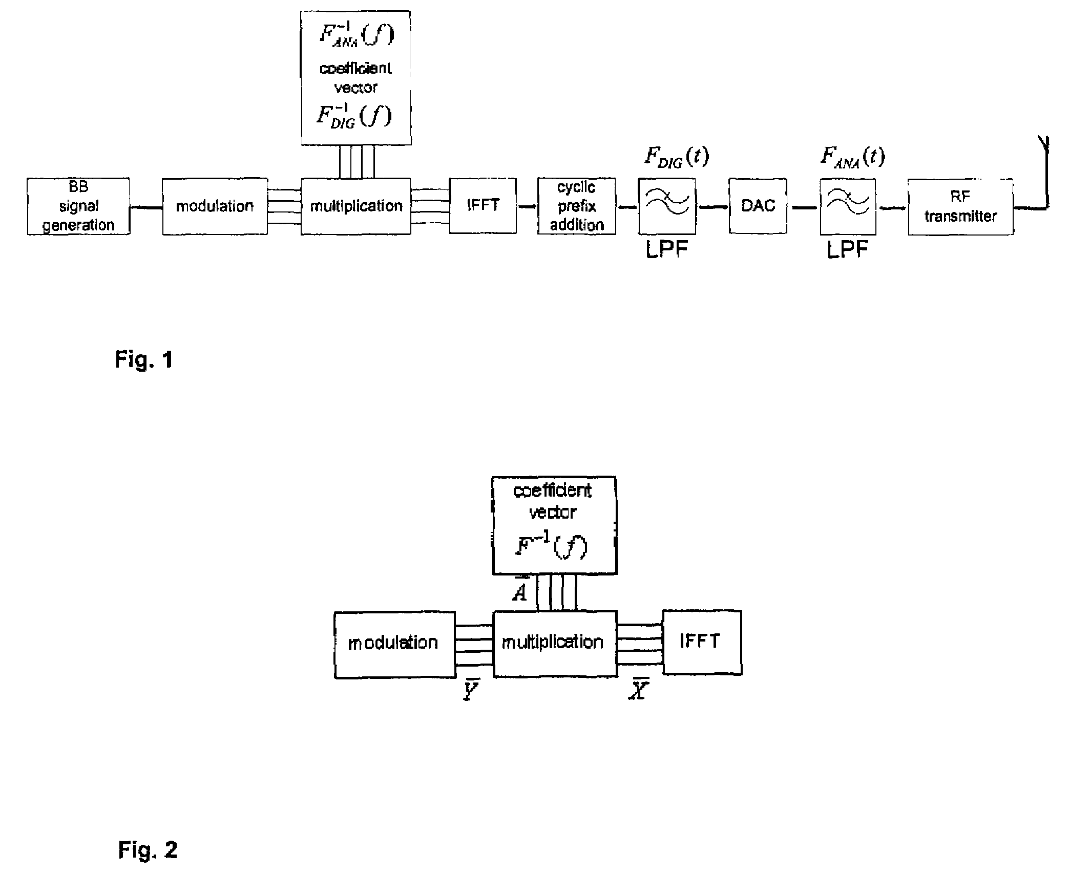
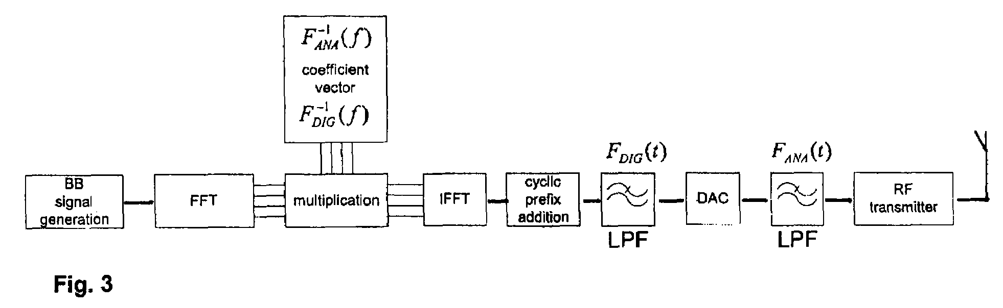
FIG. 1 shows a simplified block diagram of a frequency domain enhanced base band filtering according to an embodiment of the present invention. Starting from the base band signal generation and ending at a radio frequency transmitter. After a modulation, the base band signal is provided in frequency domain. In this embodiment, the way of obtaining a simpler filtering, either in digital or analog domain, is to allow significantly greater amplitude variation in the pass band of the filter while maintaining a large enough attenuation in the stop band. In order to maintain the original frequency response of the base band, the frequency domain base band signal after modulation is multiplied by an inverse transfer function of the simplified filtering in frequency domain. In FIG. 1, the inverse transfer function is shown as a coefficient vector F−1ANA(f) (analog domain) and F−1DIG(f) (digital domain). In the following, the filter used for the simplified filtering will be referred to as “en...


PUM


Abstract

Disclosed is a base band filter apparatus and a method for base band filtering comprising filtering a base band signal in time domain, said filtering including a filter transfer function (F), wherein the base band signal is provided in frequency domain, the frequency domain base band signal is multiplicated by an inverse filter transfer function (F−1), and the signal provided as the result of said multiplication is converted from frequency domain to time domain and provided to said filtering.

Description

FIELD OF THE INVENTIONThis application claims priority from foreign European Patent Application No. EP 06009160.0. The present invention relates to base band filters and filtering methods. In particular, the present invention relates to base band filters and methods that filter base band signals in the time domain and include a filter transfer function.BACKGROUND OF THE INVENTIONWireless communication systems typically include transmitters that have to generate signals which are strictly limited to the specified frequency channel in order to avoid interference with other users. For this reason, the transmitters typically have radio frequency filters in order to attenuate interference signals between different communication systems such as GSM (global system for mobile communication) and the transmitting and receiving channels within a system. The interference between different users operating within the same channel is limited by the use of base band filters. Since the maximum data ...

Claims


Application Information

Patent Timeline
Patent Type & Authority Patents(United States)
IPC IPC(8): H04B1/00
CPCH03H17/0213H04L27/2626
Inventor URVAS, ILKKA ERIK
Owner NOKIA TECH OY
Learn More