
Method and device for blow-molding containers

Active Publication Date: 2016-06-07
KHS GMBH
View PDF28 Cites 0 Cited by
  • Summary
  • Abstract
  • Description
  • Claims
  • Application Information

AI Technical Summary

Benefits of technology

The present invention provides a blow molding device that has a simple structural configuration and can be easily assembled and retrofitted. The device has individual storages for each blow molding station, which enables a modular construction and prevents complex circuitry or couplings. The device also has a simple cooling mechanism and avoids the use of movable feeding elements. Overall, this invention simplifies the construction and operation of blow molding devices.

Problems solved by technology

These hot blow molds have the result that solidification of the material of the blow molded containers takes place only relatively slowly.

Method used


Image

  • Method and device for blow-molding containers
  • Method and device for blow-molding containers
  • Method and device for blow-molding containers

Examples


Embodiment Construction

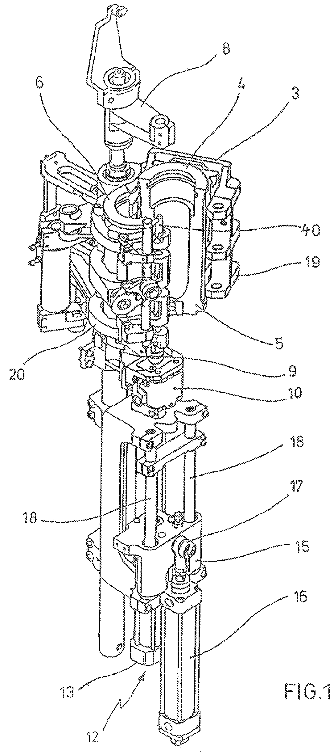
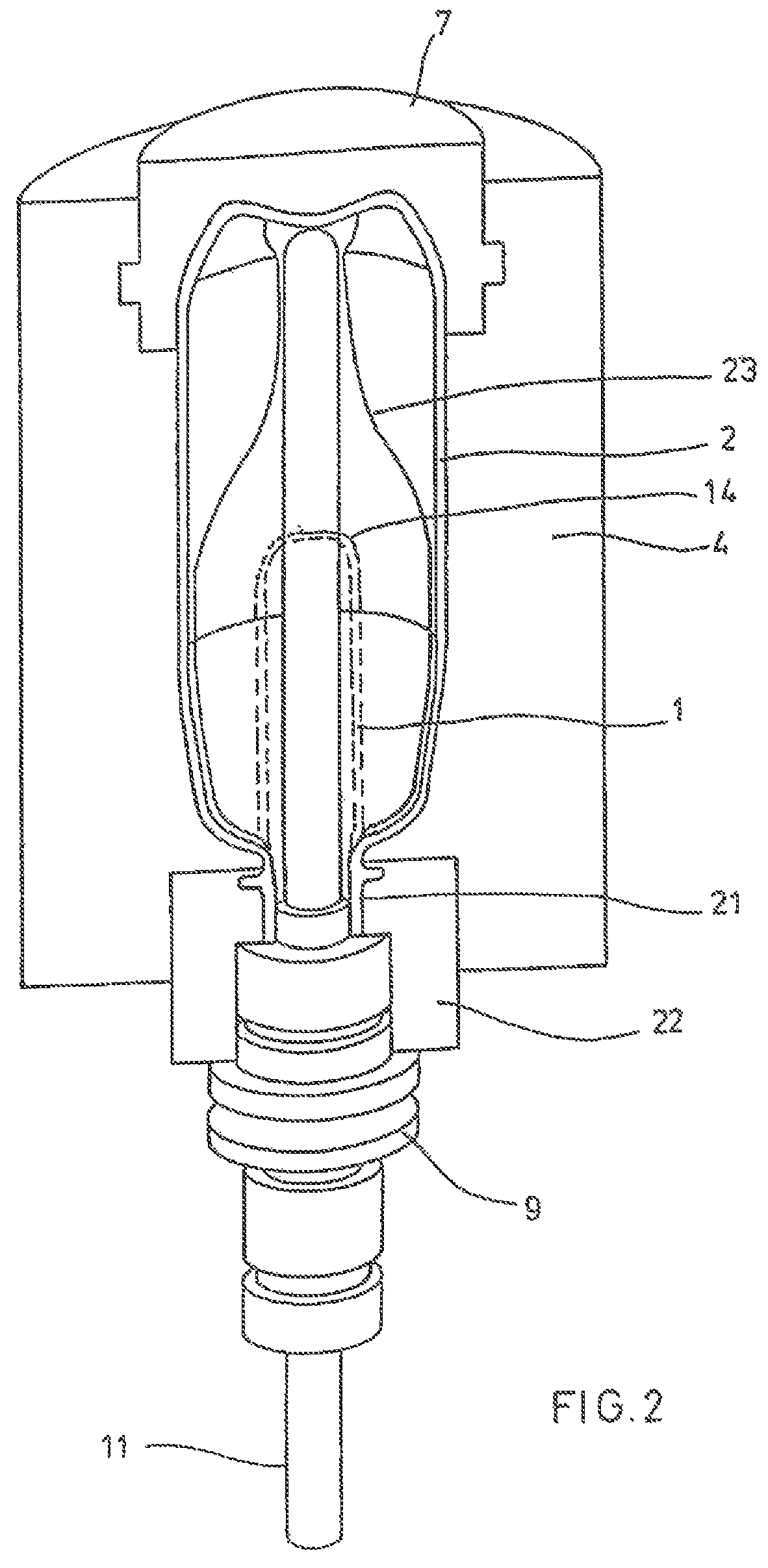
[0036]The principal construction of a device for deforming preforms 1 into containers 2 is illustrated in FIG. 1 and FIG. 2.

[0037]The device for forming containers 2 consists essentially of a blow molding station 3 which is provided with a blow mold 4 into which a preform 1 can be placed. The preform 1 may be an injection molded piece of polyethylene terephthalate. For facilitating placement of the preform 1 in the blow mold 4 and for facilitating removal of the finished container 2, the blow mold 4 is composed of mold halves5, 6 and a bottom part 7, which can be positioned by a lifting device 8. The preform 1 can be held in the area of the blow molding station 3 by a transport mandrel 9, which together with the preform 1, travels through a plurality of treatment stations within the device. However, it is also possible to place the preform 1, for example, though tongs or other manipulating means directly into the blow mold 4.

[0038]For facilitating a supply of compressed air, a conne...


PUM

PropertyMeasurementUnit
Pressureaaaaaaaaaa
Volumeaaaaaaaaaa

Abstract

The invention relates to a method and device used to blow-mold containers. After thermal conditioning, a preform is shaped into the container inside a blow mold by the effect of blowing pressure. Required blowing gas is introduced into an interior of the preform through a connecting element. After the blow-molding, a purging gas is conducted through the interior of the container. A plurality of blowing stations are used, and, for at least one of the blowing stations, at least part of the required amount of the purging gas is stored in a storage volume associated only with said blowing station.

Description

[0001]The present application is a 371 of International application PCT / DE2011 / 000047, filed Jan. 17, 2011, which claims priority of DE 10 2010 007 542.6, filed Feb. 8, 2010, the priority of these applications is hereby claimed and these applications are incorporated herein by reference.BACKGROUND OF THE INVENTION[0002]The invention relates to a method for blow molding containers, wherein a preform is deformed after thermal conditioning within a blow mold, arranged in the area of a blow molding station, by the influence of blow molding pressure in the container, and wherein a blow molding gas is conducted through a connecting element into the interior of the preform and wherein, after blow molding, a rinsing gas is conducted through the interior of the container, and wherein a plurality of blow molding stations are used.[0003]Moreover, the invention relates to a device for blow molding containers which includes at least two blow molding stations which each have at least one blow mol...

Claims


Application Information

Patent Timeline
IPC IPC(8): B29C49/66B29C49/12B29C49/06B29C49/60
CPCB29C49/66B29C49/06B29C49/12B29C2049/6027B29C2049/6615Y02P70/271Y02P70/10B29C49/42855B29C2949/0715B29C2049/7831B29C2049/7832
Inventor GODAU, GUNTHERLINKE, MICHAELKLATT, DIETERLITZENBERG, MICHAELBALKAU, KARL-HEINZ
Owner KHS GMBH
Learn More