Plasma display device

a display device and plasma technology, applied in the direction of casings/cabinets/drawers, instruments, casings/cabinets/drawers, etc., can solve the problems of weak mechanical rigidity of the display panel with respect to external impact, noise, etc., and achieve the effect of preventing vibrational nois

Inactive Publication Date: 2008-08-07
SAMSUNG SDI CO LTD
View PDF0 Cites 35 Cited by
  • Summary
  • Abstract
  • Description
  • Claims
  • Application Information

AI Technical Summary

Benefits of technology

[0013]The present invention provides a plasma display device capable of reducing noise transfer from a flexible printed circuit (FPC) to the chassis base, the FPC connecting printed circuit board assemblies to electrodes of the plasma display panel.
[0016]The plasma display device can also include comprising a driver IC (integrated circuit) mounted on the FPC and facing the second surface of the sub chassis. The plasma display device can also include thermal grease arranged between the driver IC and the second surface of the sub chassis and a thermally conductive pad attached to a side of the driver IC opposite to that of the thermal grease. The plasma display device can also include a cover plate covering the FPC, supporting the thermally conductive pad and adhering to the third surface of the sub chassis. The plurality of electrodes can include a plurality of address electrodes extending in a direction perpendicular to a plurality of discharge electrodes. The FPC can include a tape carrier package, the plasma display device further comprising a driver IC (integrated circuit) mounted on the FPC. The second and third surfaces of the sub chassis can be connected to each other in a shape of curve. The spacer can be adapted to prevent vibrational noise generated in the FPC from reaching either the chassis or the sub chassis.

Problems solved by technology

Since the plasma display panel seals two facing glass substrates together, and since a discharging space is formed between the glass substrates, the plasma display panel has weak mechanical rigidity with respect to external impact.
Accordingly, noise occurs.

Method used


Image

  • Plasma display device
  • Plasma display device
  • Plasma display device

Examples


Embodiment Construction

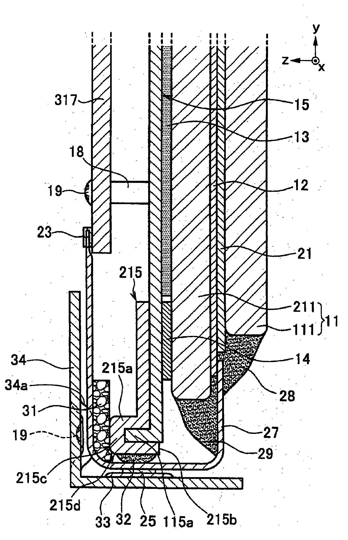
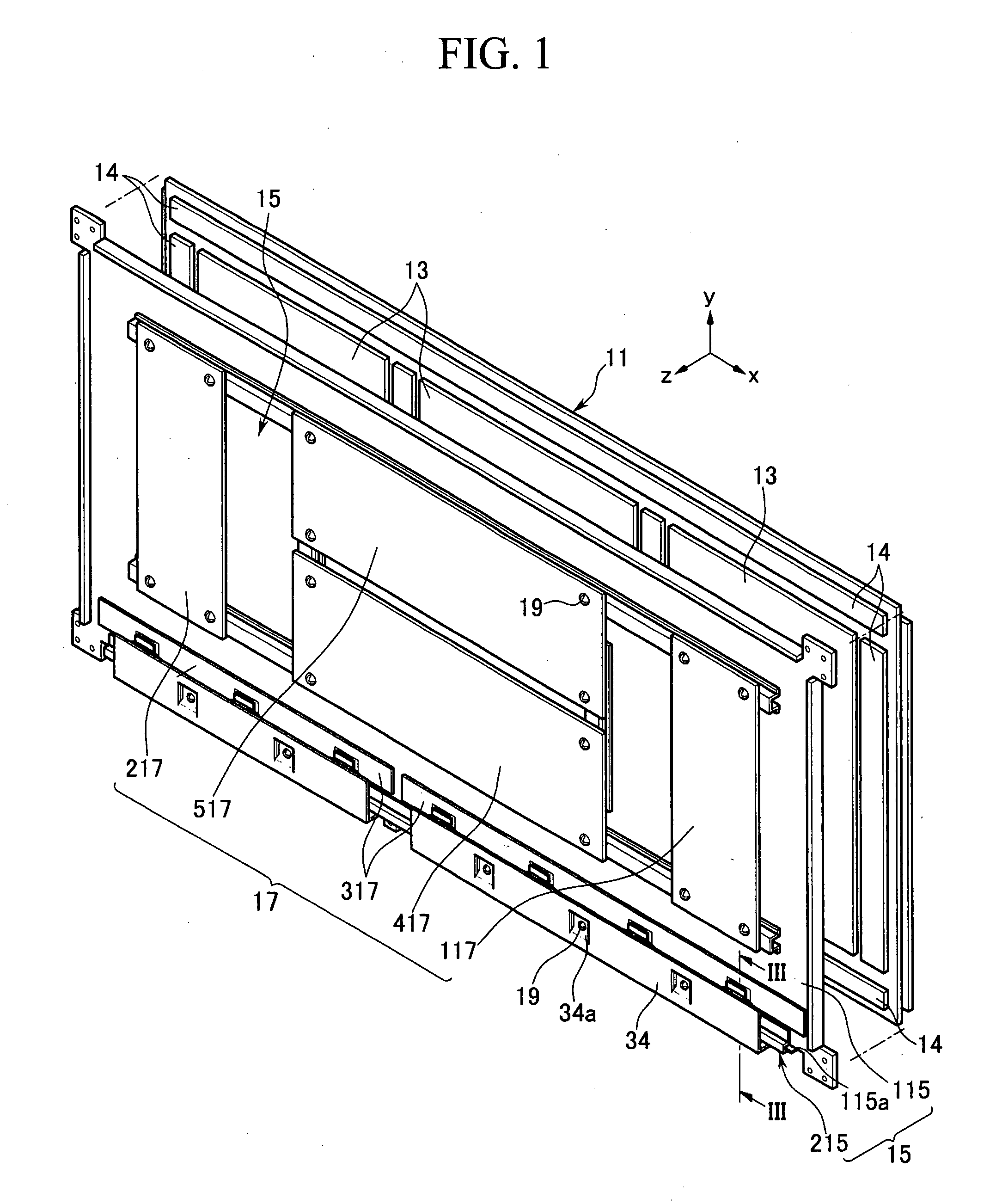
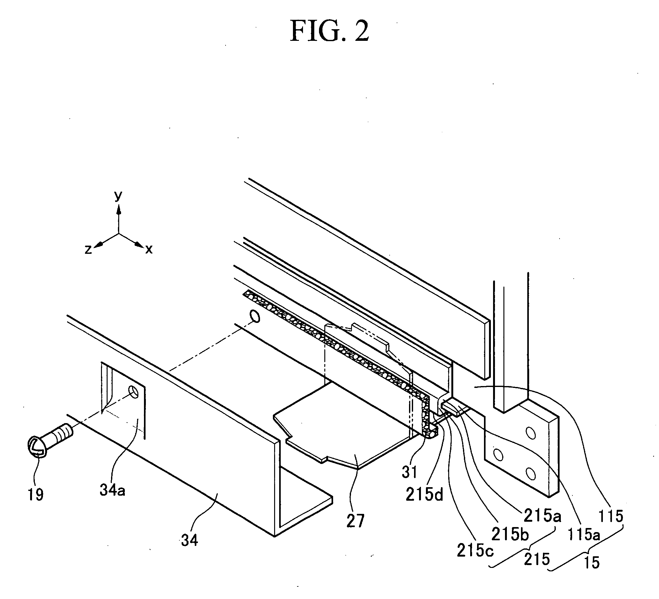
[0022]Turning now to FIGS. 1 and 2, FIG. 1 is a perspective view of a plasma display device according to an embodiment of the present invention and FIG. 2 is an exploded perspective view illustrating a sub chassis, a spacer, and a cover plate of the plasma display device of FIG. 1. Referring to FIGS. 1 and 2, the plasma display device includes a plasma display panel 11 for displaying an image using gas discharge, heat dissipating sheets 13, a chassis base 15, and printed circuit board assemblies 17.

[0023]The heat dissipating sheets 13 are disposed on a rear surface of the plasma display panel 11. The heat dissipating sheets 13 conduct and diffuse heat in a planar direction generated in the plasma display panel 11 due to gas discharge. In order to conduct and diffuse the heat generated in the plasma display panel 11, the heat dissipating sheets 13 are made out of an acrylic heat dissipating material, a graphite heat dissipating material, a metallic heat dissipating material, or a car...


PUM


Abstract

A design for a plasma display device that attenuates noise generated in a flexible printed circuit (FPC) so that the noise does not reach the chassis base, the FPC connecting a printed circuit board assembly to electrodes within the plasma display panel. The plasma display device includes a spacer made out of non woven fabric and located between the FPC and the chassis.

Description

CLAIM OF PRIORITY[0001]This application makes reference to, incorporates the same herein, and claims all benefits accruing under 35 U.S.C. §119 from an application for PLASMA DISPLAY DEVICE earlier filed in the Korean Intellectual Property Office on 7 Feb. 2007 and there duly assigned Serial No. 10-2007-0012670.BACKGROUND OF THE INVENTION[0002]1. Field of the Invention[0003]The present invention relates to a plasma display device, and more particularly, to a plasma display device capable of reducing the transfer of noise from a flexible printed circuit (FPC) to a chassis base, the FPC connecting printed circuit board assemblies to electrodes of the plasma display panel.[0004]2. Description of the Related Art[0005]Generally, a plasma display device includes a plasma display panel for displaying an image, a chassis base which is fixed to the plasma display panel to support the plasma display panel, and a plurality of printed circuit board assemblies, which are mounted on the chassis b...

Claims


Application Information

Patent Timeline
Patent Type & Authority Applications(United States)
IPC IPC(8): H05K5/02
CPCH05K9/0096H01J11/34H01J11/46H05K7/20963H05K2201/2045
Inventor LEE, SANG-GU
Owner SAMSUNG SDI CO LTD
Why Eureka
Try Eureka