Surgical Tool Arrangement
- Summary
- Abstract
- Description
- Claims
- Application Information
AI Technical Summary
Benefits of technology
Problems solved by technology
Method used
Image
Examples
third embodiment
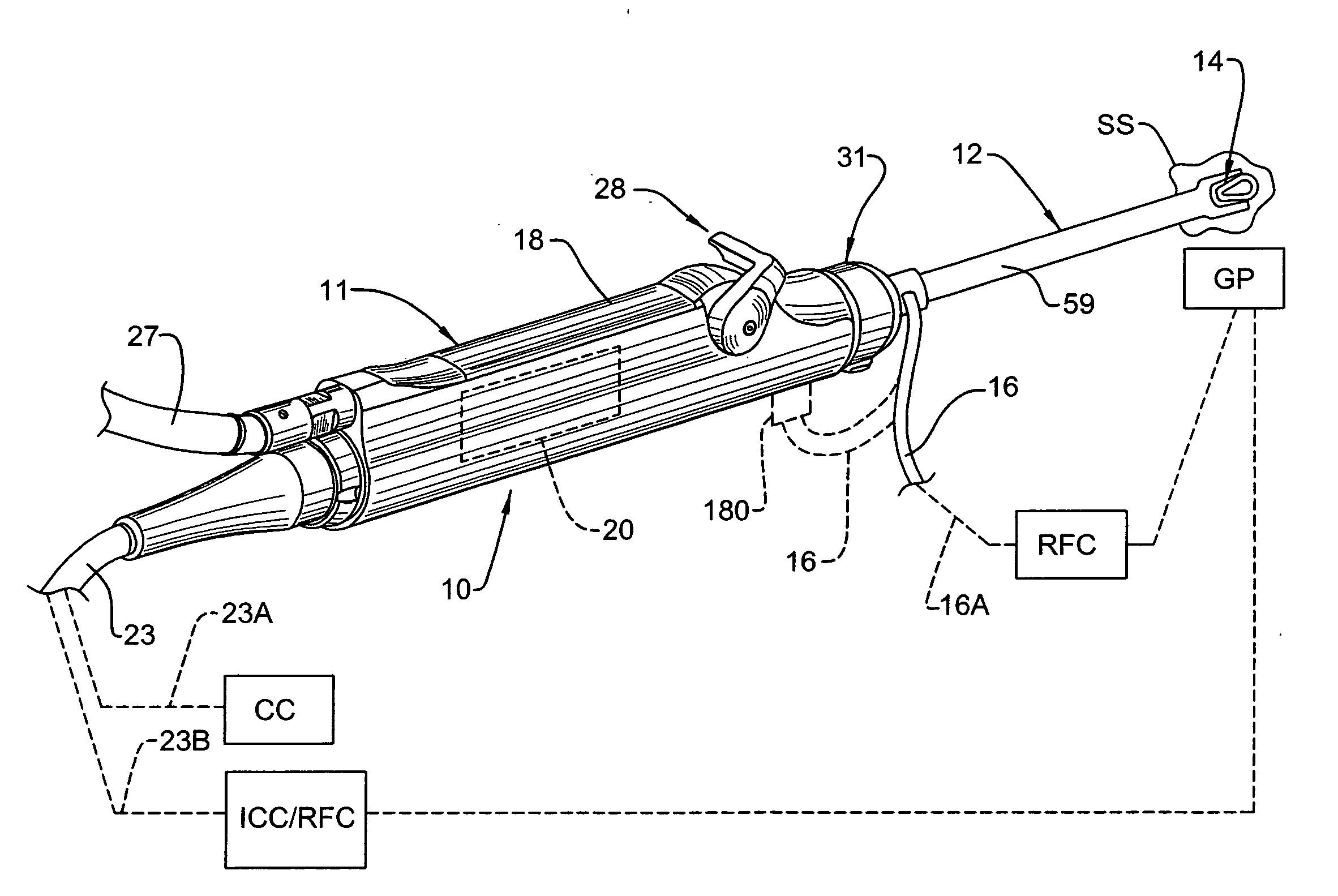
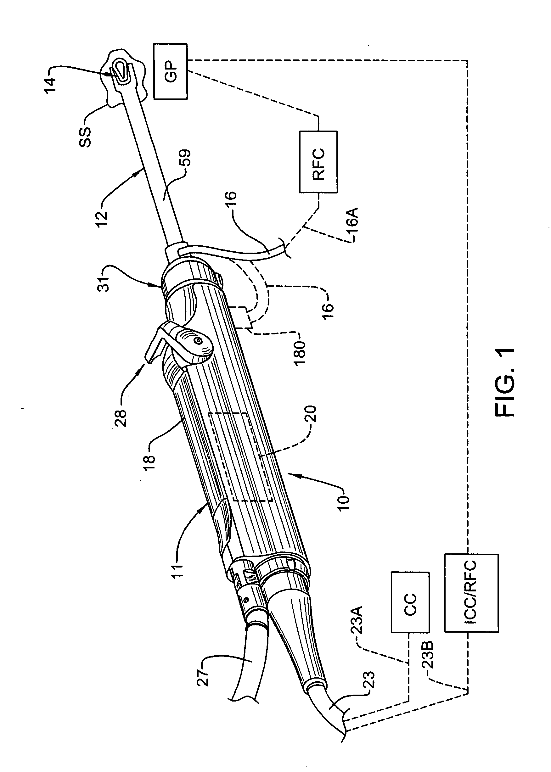
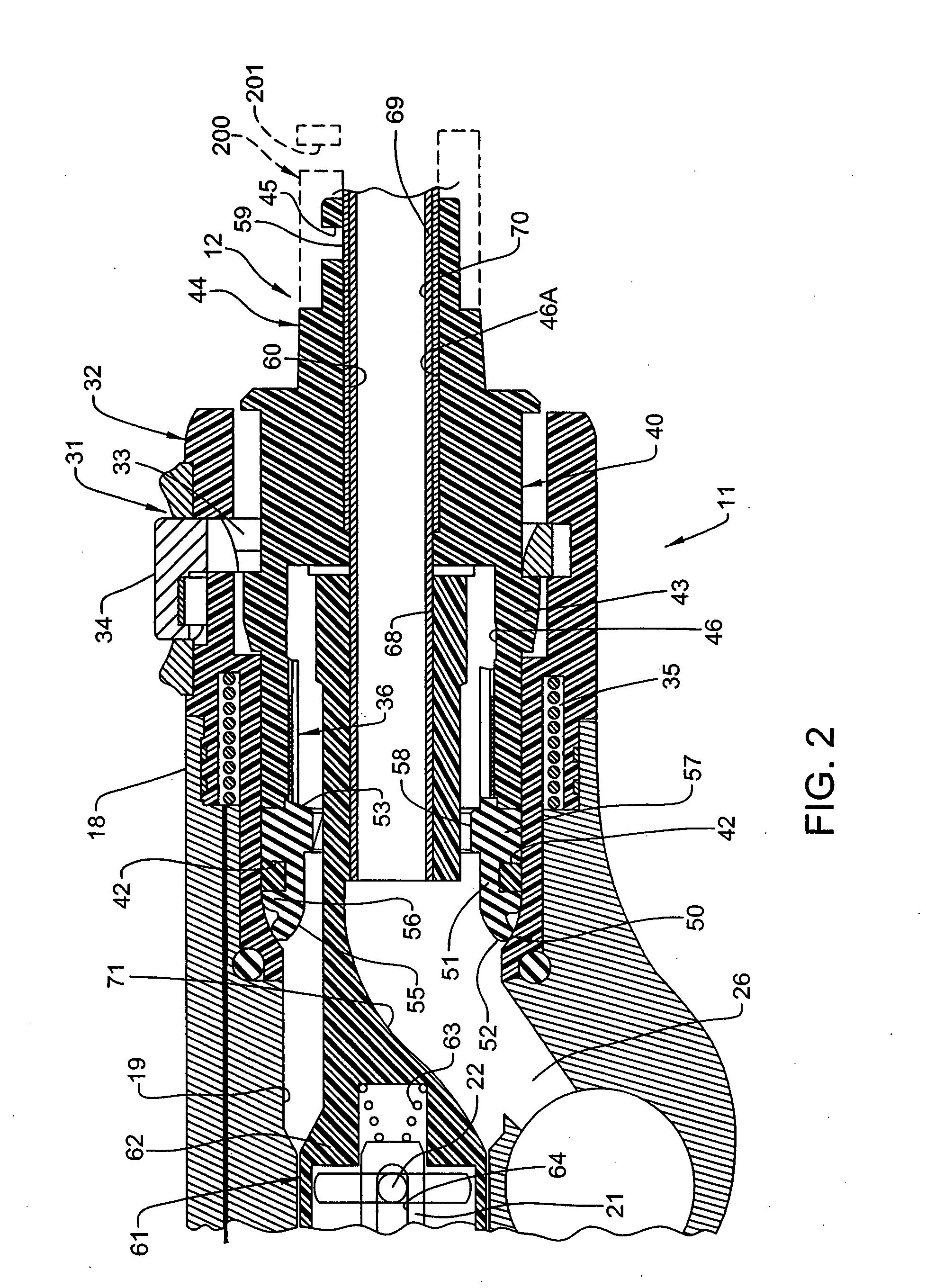
[0075]FIGS. 10 and 11 illustrate a combined electrosurgical tool and cutting instrument 110 which may be utilized with handpiece 11. In this embodiment, the instrument 110 includes an inner housing tube 111 constructed of metal, for example stainless steel. An outer housing tube 112 is disposed over the inner tube 111 and is non-movable relative thereto. Outer tube 112 is constructed of rigid plastic, and includes a conductive wire mesh or coil 113 embedded therein. The respective tubes 111 and 112 are then cut as described above to define a window 114 at the distal end of instrument 110, as in the above embodiments. The cutting process exposes a ring-shaped area 115 of inner tube 111, inwardly of the edge of outer tube 112. Area 115 defines a cutting edge 116 which cooperates with the cutting head 71 of cutting element 15 to sever tissue. After cutting of the instrument 110 to define window 114, the plastic of outer tube 112 is removed around portions of the wire mesh 113 to define...
first embodiment
[0076]The first three embodiments of the combined electrosurgical tool and cutting instrument are disclosed herein as being utilized as monopolar instruments in conjunction with a patient grounding pad (GP). However it may be possible or desirable to utilize some of these instruments as bipolar instruments. For example, and with respect to FIGS. 5-7, the housing tube 80 and its exposed ring-like portion 82A can be used as the return path for the electrical current delivered to the surgical site (SS) via electrode arrangement 14. In this instance, the insulating layer 81 can be removed from (or not initially applied to) an area located on the proximal end of housing tube 80 inside head 44 of hub 40, and then electrically connected to cable 16, wherein cable 16 would be configured to both deliver electrical current to electrode arrangement 14 from RF control (RFC) and return current from housing tube 80 to RF control (RFC).
[0077]With respect to the third embodiment illustrated in FIGS...
fourth embodiment
[0078]FIGS. 12 and 13 illustrate a combined electrosurgical and cutting instrument 120 which may be utilized with handpiece 11. In this embodiment, instrument 120 is a multi-layer component. More specifically, instrument 120 includes an innermost housing tube 121 of a conductive material, such as stainless steel. The outer surface of tube 121 is coated with an insulating layer 123. The insulating layer 123 is covered with a conductive layer 124, such as copper, and the conductive layer 124 is covered with a further insulating layer 125. In this embodiment as in the prior embodiments, the instrument 120 is cut at its distal end to define a window 127, which cutting process results in the formation of an annular electrode 129 defined by the exposed distal end of the conductive layer 124. The exposed distal end of inner housing tube 121 defines a ring-like area 130, the innermost edge of which defines a cutting edge 131 which cooperates with cutting head 71 of cutting element 15 to sev...
PUM
 Abstract
Description
Claims
Application Information
 - R&D
- Intellectual Property
- Life Sciences
- Materials
- Tech Scout
- Unparalleled Data Quality
- Higher Quality Content
- 60% Fewer Hallucinations
Browse by: Latest US Patents, China's latest patents, Technical Efficacy Thesaurus, Application Domain, Technology Topic, Popular Technical Reports.
© 2025 PatSnap. All rights reserved.Legal|Privacy policy|Modern Slavery Act Transparency Statement|Sitemap|About US| Contact US: help@patsnap.com


