Storage control unit and data management method

a storage control unit and data management technology, applied in the direction of memory address/allocation/relocation, liquid/fluent solid measurement, instruments, etc., can solve the problems of increasing the cost of manufacturing the storage control unit, the loss of data stored in the cache memory, and the comparatively large capacity of the battery, so as to achieve the effect of adequate saving and low capacity of non-volatile memory

Inactive Publication Date: 2008-08-07
HITACHI LTD
View PDF5 Cites 69 Cited by
  • Summary
  • Abstract
  • Description
  • Claims
  • Application Information

AI Technical Summary

Benefits of technology

[0011]The present invention was made in view of the above problems, its object being to provide a technique whereby the data stored in cache memory can be adequately saved, while keeping the capacity of the non-volatile memory low.

Problems solved by technology

In a storage control unit comprising volatile memory as the cache memory if the supply of power to the cache memory ceases due for example to a fault of the external power supply, the data stored in the cache memory is lost.
However, since supply of power to the cache memory must be maintained until the fault is cleared, the capacity of the battery must be comparatively large.
This leads to the problem that the cost of manufacturing the storage control unit is increased.
This increases the manufacturing cost of the storage control unit.
On the other hand, if, in order to keep down the cost of manufacture, it is arranged to save the data by providing non-volatile memory of smaller capacity than the cache memory, the data of the cache memory cannot be adequately saved to the non-volatile memory, so there is the risk of producing a situation in which necessary data is lost.

Method used


Image

  • Storage control unit and data management method
  • Storage control unit and data management method
  • Storage control unit and data management method

Examples


first embodiment

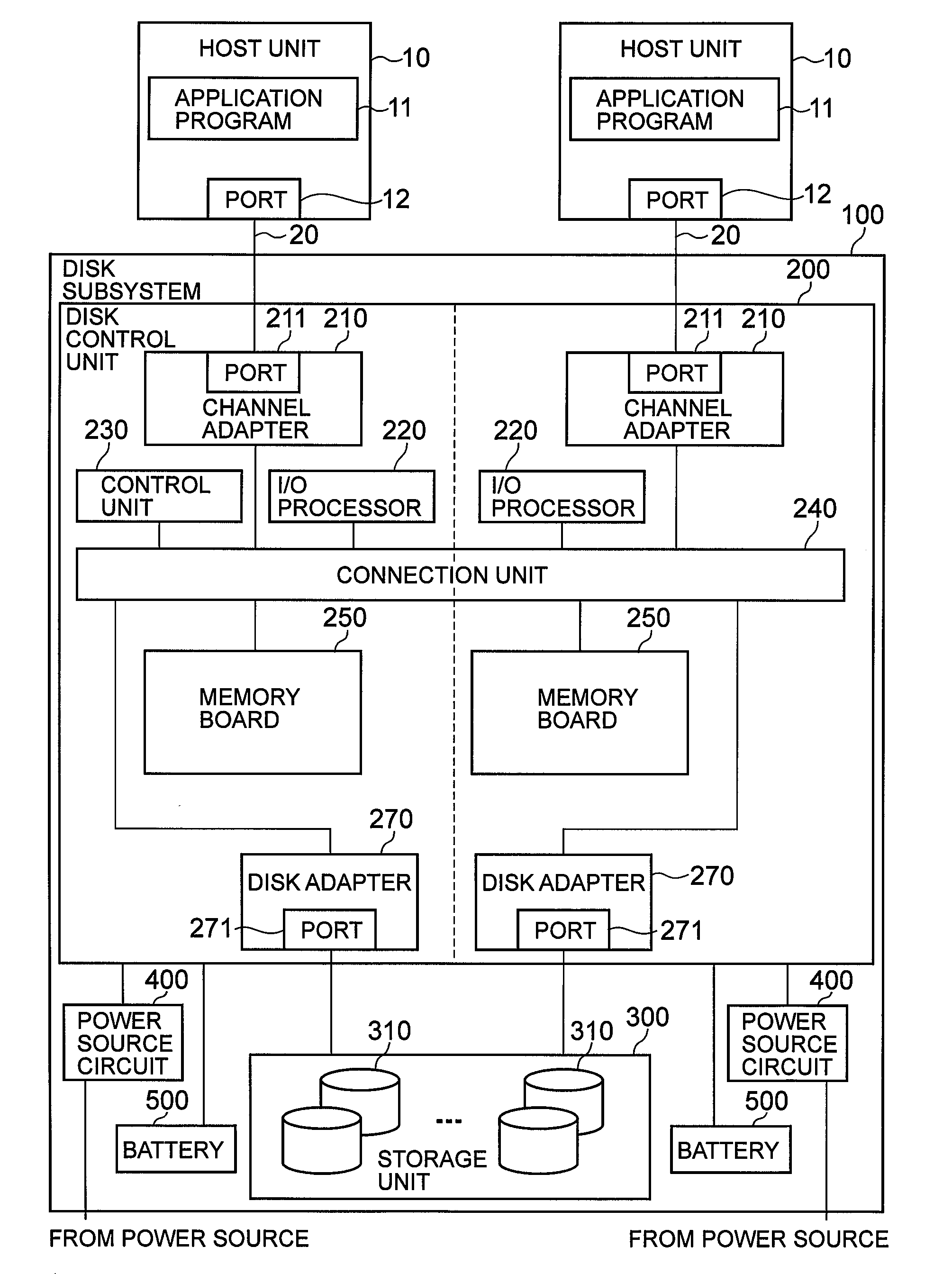
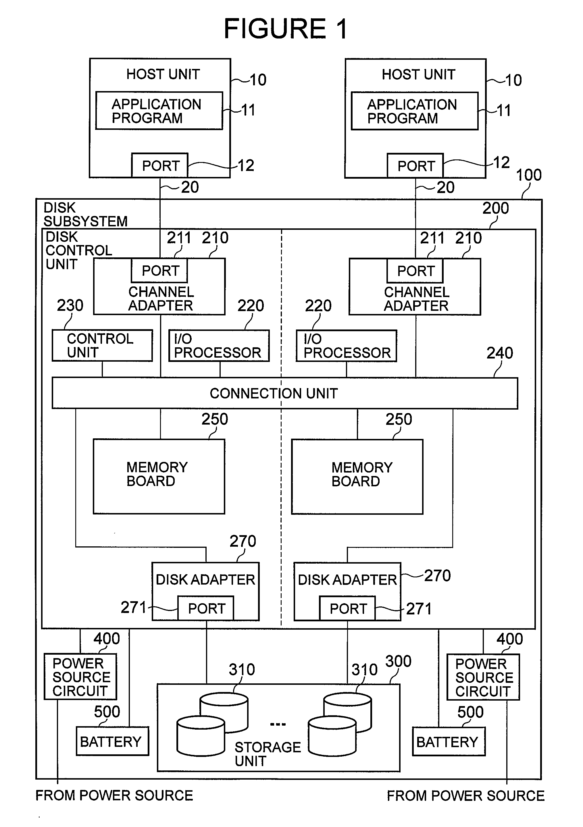
[0034]FIG. 1 is a structure diagram of a computer system according to a first embodiment of the present invention.

[0035]A computer system comprises one or more host units 10 and one or more disk subsystems 100. The host unit 10 and the disk subsystems 100 are connected through a network 20. The network 20 may be any of for example a SAN (storage area network), LAN (local area network), the Internet, a private line (least line) or public line, so long as it is capable of performing data communication. Also, as the protocol in the network 20, any protocol may be employed that is capable of exchange of data between the host unit 10 and the disk subsystems 100, such as for example fiber channel protocol or TCP / IP protocol. It should further be noted that, instead of the network 20, a direct connection by means of a cable of the host unit 10 and disk subsystems 100 could be employed.

[0036]The host unit 10 comprises for example a CPU (central processing unit), not shown, memory, not shown...

second embodiment

[0121]FIG. 12 is a structure diagram of a computer system according to a second embodiment of the present invention. Functional sections that are the same as in the case of the first embodiment are given the same reference symbols.

[0122]The disk control unit 202 comprises a plurality of clusters 203 having the same construction. Each cluster 203 is constituted by for example a single control board subsystem control board, and comprises: a channel adapter 210, an I / O processor 280, a subsystem controller 281, volatile memory 282, non-volatile memory 283, a disk adapter 270 and a voltage monitoring control unit 257.

[0123]A power source circuit 400 supplies power that is supplied from for example an external commercial power source to the various units of the disk control unit 202. In this embodiment, the power source circuit 400 is arranged to supply power to the various units of a plurality of clusters 203 without duplication. It should be noted however that, by providing more than o...


PUM


Abstract

An I/O processor determines whether or not the amount of dirty data on a cache memory exceeds a threshold value and, if the determination is that this threshold value has been exceeded, writes a portion of the dirty data of the cache memory to a storage device. If a power source monitoring and control unit detects a voltage abnormality of the supplied power, the power monitoring and control unit maintains supply of power using power from a battery, so that a processor receives supply of power from the battery and saves the dirty data stored on the cache memory to a non-volatile memory.

Description

CROSS-REFERENCE TO PRIOR APPLICATION[0001]This application relates to and claims the benefit of priority from Japanese Patent Application No. 2007-27620, filed on Feb. 7, 2007, the entire disclosure of which is incorporated herein by reference.BACKGROUND OF THE INVENTION[0002]A storage control unit may have for example a plurality of storage devices such as hard disk drives connected with it. On receiving a write command from a host computer, the storage control unit writes data to at least one storage device of the plurality of storage devices, and, on receiving a read command from the host computer, reads data from at least one storage device of the plurality of storage devices and transmits this data to the host computer.[0003]Such a storage control unit comprises a cache memory for temporarily storing the data that is written to the storage devices in response to a write command or for temporarily storing the data that is read from the storage devices in response to a read comma...

Claims


Application Information

Patent Timeline
Patent Type & Authority Applications(United States)
IPC IPC(8): G06F12/08G06F1/32G06F12/00G06F11/30
CPCG06F11/1441G06F12/0804Y02B60/1225G06F2201/81G06F12/0866Y02D10/00
Inventor IIDA, JUNICHIJIANG, XIAOMING
Owner HITACHI LTD
Why Eureka
Try Eureka