Bathroom floor panel

a floor panel and bathroom technology, applied in the direction of flooring, treads, constructions, etc., can solve the problems of large amount of water drops remaining on the floor surface, user discomfort, and water used in the shower room or the unit bathroom to be repelled, so as to prevent slippage

Inactive Publication Date: 2008-08-14
TOTO LTD
View PDF28 Cites 75 Cited by
  • Summary
  • Abstract
  • Description
  • Claims
  • Application Information

AI Technical Summary

Benefits of technology

[0033]In order to solve the above-described problem, a bathroom floor panel according to a first aspect of the present invention is comprised of projections for preventing slippage provided on the surface of the panel; channels connecting to a drain hole or a drain groove and provided between the projections; and irregular-shaped portions for breaking the surface tension of waterdrops provided at least on the channels.
[0034]With this structure, it is possible to achieve both of a non-slip effect and an effect of preventing the surface from remaining wet with water drops that have not drained.
[0035]Further, according to the first aspect of the present invention, the irregular-shaped portions for breaking the surface tension of waterdrops are formed in a direction resisting the water flow. With this, it is possible to control the flow velocity of water which flows in the channels, prevent the water from being disconnected and remaining as isolated drops, and thereby dry the surface of the floor in a shorter period of time.
[0036]A bathroom floor panel according to a second aspect of the present invention is comprised of projections for preventing slippage and breaking the surface tension of waterdrops provided on the surface of the panel; channels connecting to a drain hole or a drain groove and provided between the projections; and a means or mechanism for reducing the flow velocity in the channels so that the water in the channels is not discontinued.
[0037]With this structure, it is possible to achieve both of a non-slip effect and an effect of quickly drying the floor after use. Because the flow velocity of the water in the channels is reduced, the time during which the channels remain continuously wetted with the water is prolonged and more of the water drops are efficiently drained from the floor surface.

Problems solved by technology

Although a steeper gradient can achieve better drainage, it causes a user to feel uncomfortable.
However, as described above, since the floor material is made of FRP which has hydrophobic (water-repellent) properties and does not absorb water, there is a tendency for some water used in a shower room or a unit bathroom to be repelled on the floor surface and gather as large water drops so as to become hard to flow.
Consequently, a large amount of water drops remain on the floor surface.
This is because water is hard to flow while bringing a dried surface into a wet state due to its surface tension or viscosity.
Such irregularities of the non-slip patterns prevent water drops from flowing, which results in a further increase in the amount of the remaining water, and consequently the problem has become more noticeable.
Also, it takes a lot of time for such water drops to dry because the amount of water is too much compared to the surface area.
The remaining water drops still remain without drying after several hours, e.g., the next morning, because the characteristics of the material of the shower room and the unit bathroom such as highly airtight properties and low water-absorbing properties have bad effects in the same way as wet dust cloths do not dry in a vinyl bag.
This is very uncomfortable and far from user-friendliness, and furthermore the inside of the bathroom is humid all the time because the moisture remains for a long period of time, which can easily cause mold to grow.
However, the shower room and the unit bathroom has such disadvantages that water within the room is hard to dry compared to a conventional bathroom.
Consequently, there is a tendency for water used in the bathroom to be repelled on the floor surface and gather as large water drops so as to become hard to flow, and a large amount of water drops remain on the floor surface without being drained.
This is because the application of preliminary waterproofing works to the bathroom space of a building has become unnecessary by using a waterproof floor pan having a floor made of a waterproof material such as an FRP.
However, although the above-described waterproof floor pan of a unit bath has good feeling in use because it is not slippery at the time of performing body-washing in a wash place or the like, the irregularities adversely affect the capability of drainage on the surface of the wash place, and thereby the water to be drained remains as an island or isolated drops on the surface.
Even on the next day, the water continues to remain without being air-dried because the drops contain a large amount of water relative to the surface area and are not easily dried.
Consequently, when a user stands on the wash place portion in the bathroom with socks on, for example to clean a bathtub, the socks will get wet, which it is very uncomfortable.
Also, it is troublesome to put off socks for every cleaning.
In particular, it has been very unpleasant for elderly people because the remaining-water is cold in the winter season.

Method used


Image

  • Bathroom floor panel
  • Bathroom floor panel
  • Bathroom floor panel

Examples


Embodiment Construction

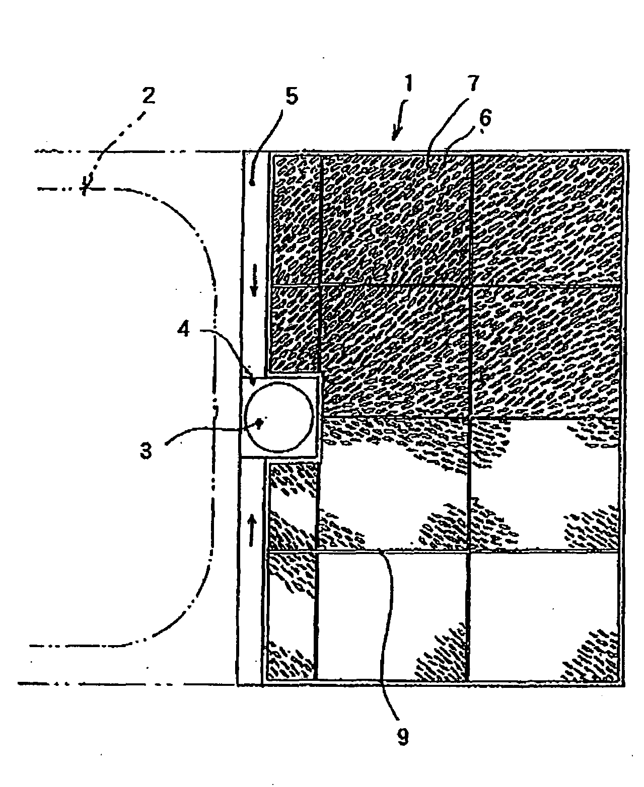
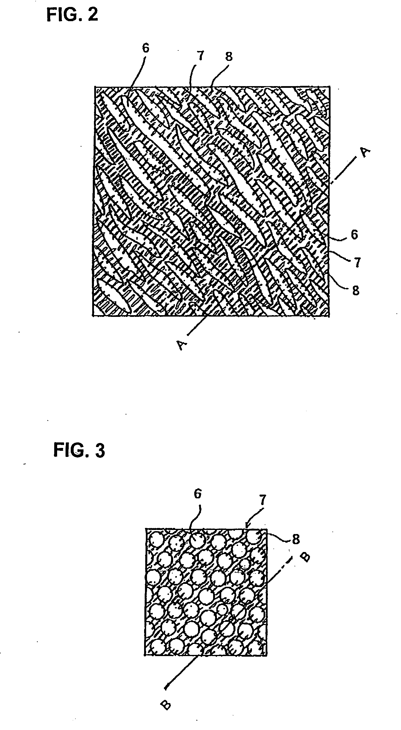
[0056]The embodiments of the present invention will now be described with reference to the appended drawings. FIG. 1 is a plan view of a bathroom floor panel according to a first aspect of the present invention; FIG. 2 is an enlarged plan view of the bathroom floor panel; FIG. 3 is an enlarged plan view of a bathroom floor panel according to another embodiment of the first aspect of the present invention; FIG. 4 is an enlarged sectional view taken along line A-A of FIG. 2; FIG. 5 is an enlarged sectional view taken along line B-B of FIG. 3; and FIGS. 6(a) to (c) show the behavior of water on a floor panel.

[0057]A floor panel 1 is prepared by molding a resin material (for example FRP) and comprised of a bathtub installing portion 2 and a water place portion adjacent thereto. The bathtub installing portion 2 may be a split type in which it is formed as a separate member from a water place side floor panel and these are connected afterwards, or a bathtub with a water place in which a b...


PUM

PropertyMeasurementUnit
humidityaaaaaaaaaa
temperatureaaaaaaaaaa
heightaaaaaaaaaa

Abstract

A bathroom floor panel for use in an airtight and water tight space is configured to be efficiently dried in a few hours under ambient conditions. When water drops onto the floor panel, the surface tension of the water is broken by irregular-shaped portions and the water spreads without forming waterdrops. Also, the irregular-shaped portions reduce the flow velocity of the water due to a gradient of the panel, so as to prevent the water flowing in channels to a drain from being discontinued. With this, although the drain velocity of the water is low, substantially no water remains as isolated drops. Further, even if some water remain on the irregular-shaped portions after the water flows out the channels to the drain, any amount of water remaining in the channels is evaporated in a relatively short period of time because the amount of the remaining water is very small.

Description

CROSS-REFERENCE TO RELATED APPLICATIONS[0001]The present application is a continuation-in-part application of pending U.S. patent application Ser. No. 10 / 479,117 filed 28 Nov. 2003, which is the U.S. National Phase of International Application PCT / JP02 / 05281 filed 30 May 2002, which claims priority under 35 USC §119 based on Japanese Patent Application Number 2001-163403, filed on 30 May 2001. The subject matter of each of the above-identified applications is incorporated by reference herein.TECHNICAL FIELD [0002]The present invention relates to a resin bathroom floor panel to be assembled as a part of a unit bath.BACKGROUND ART [0003]The floor panel of the present invention is applied to a booth, i.e., a prefabricated airtight unit room, whose components or parts are fabricated at a factory, which can be readily built on site by only assembling the components or parts.[0004]Examples of such a booth include a unit bathroom and a shower room. The details thereof will be explained her...

Claims


Application Information

Patent Timeline
Patent Type & Authority Applications(United States)
IPC IPC(8): E04F15/00
CPCE04F15/02E04F15/02161E04F15/02172E04F15/02188E04F15/105
Inventor KITAKADO, TOSHIMI
Owner TOTO LTD
Why Eureka
Try Eureka