
Fourier-based misfire detection strategy

a fourier-based misfire detection and misfire detection technology, applied in the direction of instruments, analogue processes for specific applications, electric/magnetic computing, etc., can solve the problems of obscuring misfire conditions, preventing accurate detection of misfire conditions, and spectral components derived from crankshaft-originated speed signals encountering difficulty in certain circumstances, so as to achieve accurate and effective misfire detection

Active Publication Date: 2008-08-14
DELPHI TECH IP LTD
View PDF11 Cites 26 Cited by
  • Summary
  • Abstract
  • Description
  • Claims
  • Application Information

AI Technical Summary

Benefits of technology

"The present invention provides a method for accurately detecting misfire in internal combustion engines across a wide range of engine speed and load, as well as for higher number of cylinder engines. The method involves producing a first signal based on the rotational characteristics of the engine crankshaft, converting it into a frequency-domain misfire detection metric, and normalizing it using a non-misfire metric. The final step involves detecting a misfire condition when the normalized misfire detection metric exceeds a predetermined threshold and identifying the origin of the misfire. Overall, the invention provides a reliable and effective means for detecting misfire in engines."

Problems solved by technology

However, such “normal” variations can nonetheless obscure variations in speed due to misfire, which can prevent accurate detection of or in other words mask misfire conditions.
Prior systems that assess only the amplitude / phase of the spectral components derived from the crankshaft-originated speed signal encounter difficulty in certain circumstances distinguishing non-misfire and misfire conditions.

Method used


Image

  • Fourier-based misfire detection strategy
  • Fourier-based misfire detection strategy
  • Fourier-based misfire detection strategy

Examples


Embodiment Construction

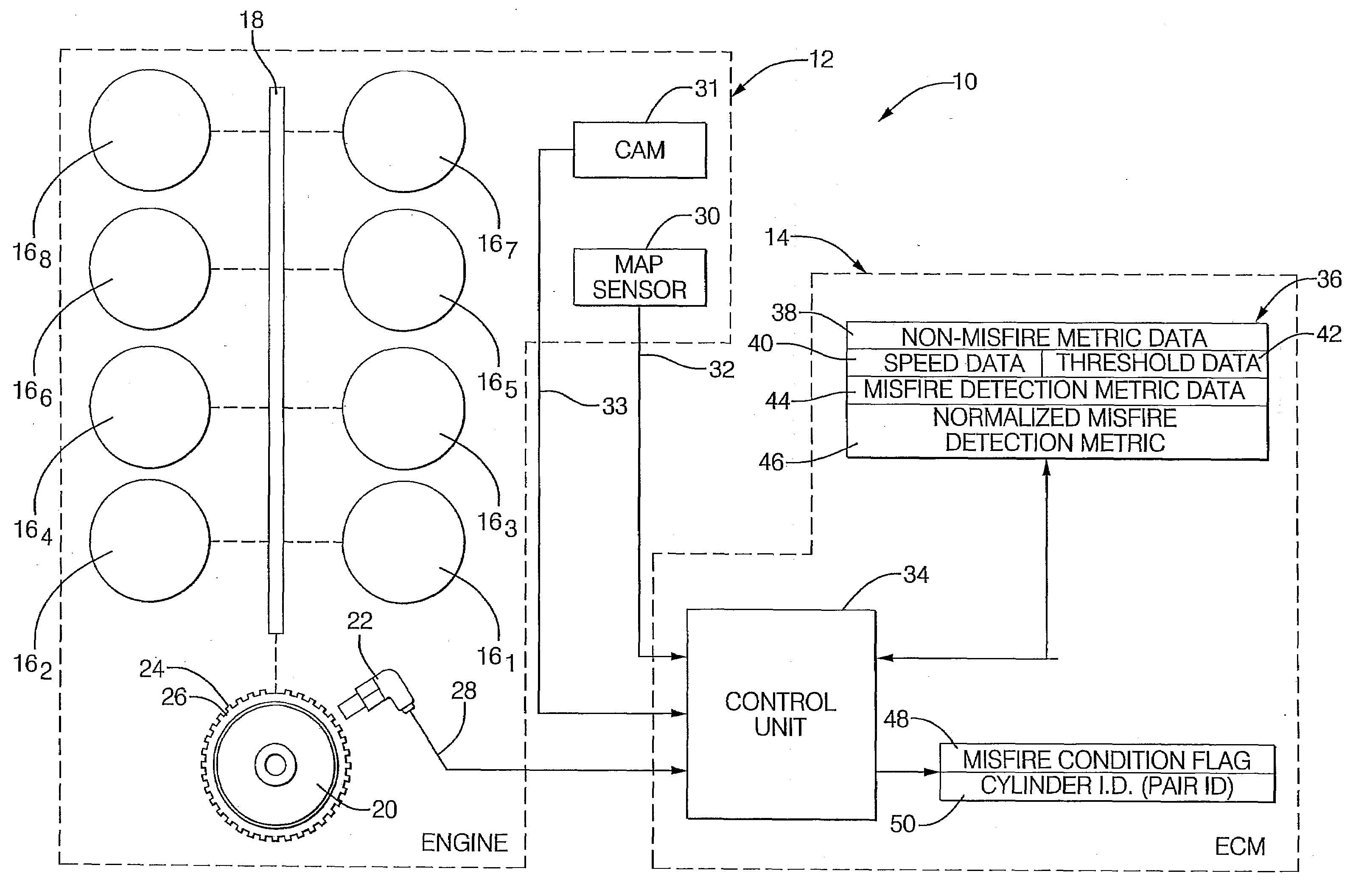
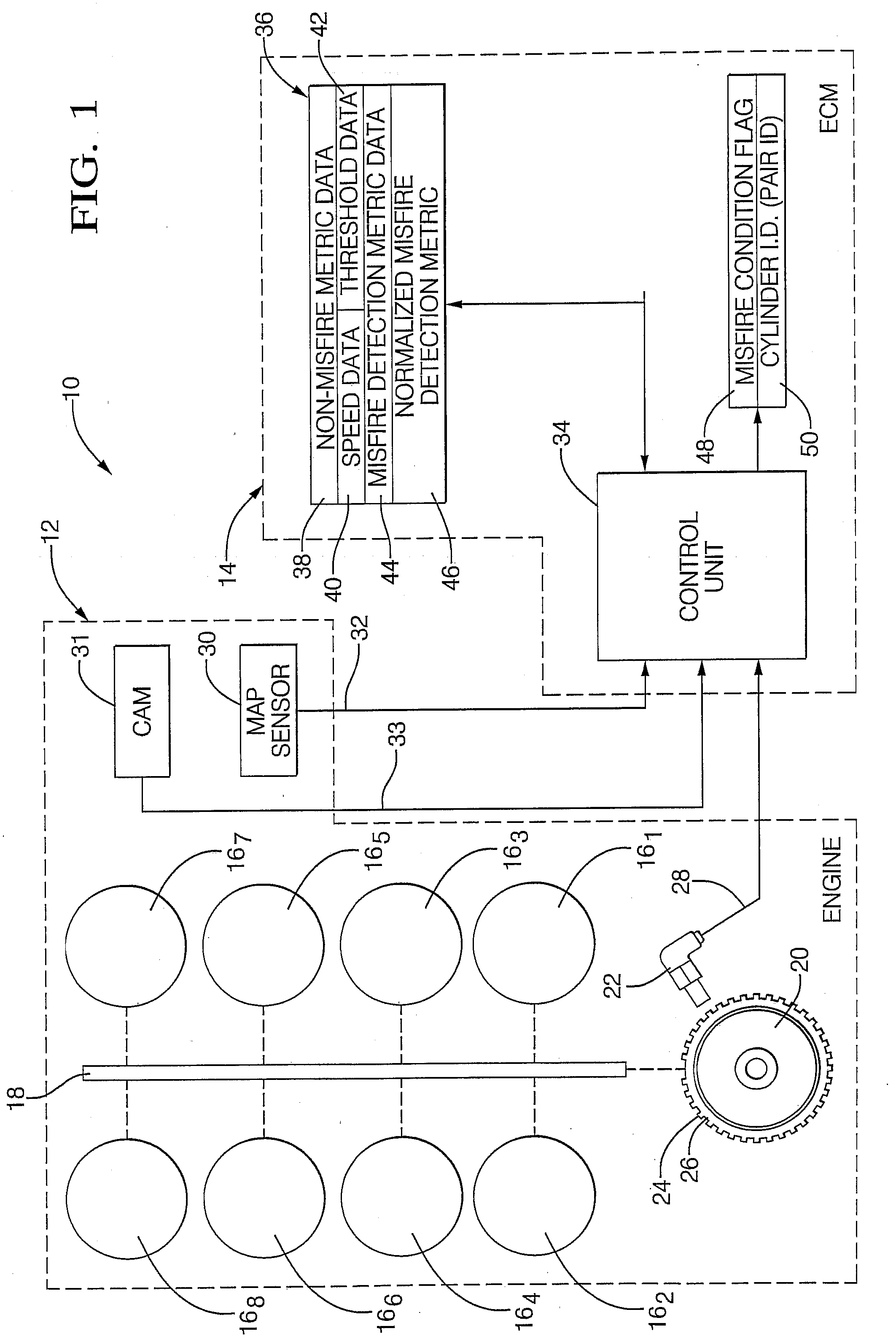
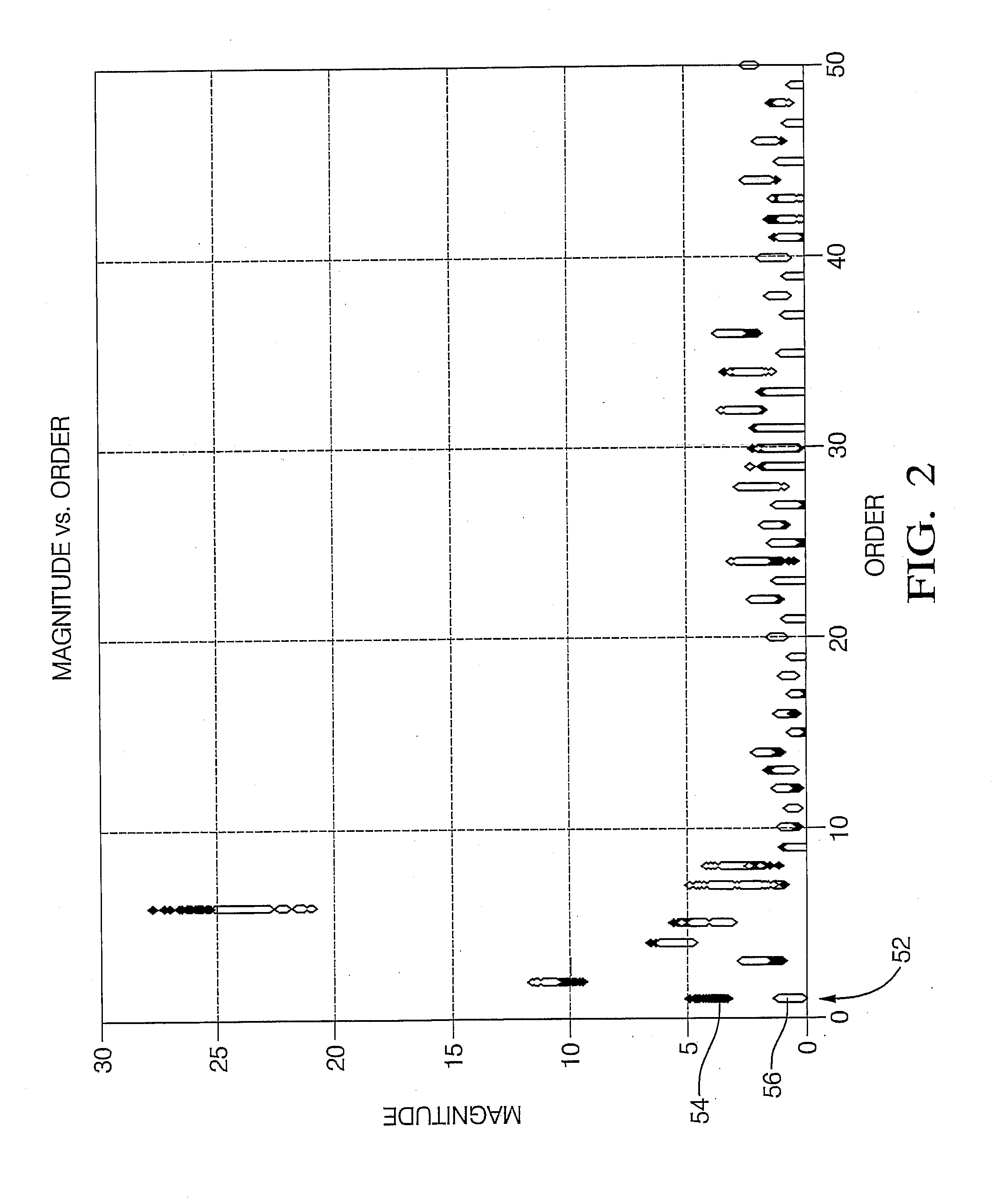
[0022]Referring now to the drawings wherein like reference numerals are used to identify identical components, FIG. 1 shows an internal combustion engine system 10 including an internal combustion engine 12 whose operation is controlled by a programmed, electronic engine control module (ECM) 14 or the like, as known generally in the art. System 10 is configured, as will be described and illustrated hereinafter, to provide improved misfire detection as to either an individual cylinder or multiple cylinder (e.g., a cylinder pair). System 10 includes improved discrimination capability that provides for more effective detection for higher number cylinder engines as well as over greater engine speed / load ranges. System 10 generally employs frequency domain, Fourier techniques to evaluate the spectral content of a crankshaft-originated speed signal. Speed fluctuations due to misfire result in certain harmonics being present in the frequency domain transformation of the crankshaft-originat...


PUM


Abstract

A computer implemented system for engine misfire detection employs a crankshaft-originated speed signal that includes normal variability due to target wheel tooth error and the like. A Discrete Fourier Transform (DFT) is performed on the speed signal to convert it into a frequency-domain raw misfire detection metric. The system is configured to normalize the raw misfire detection metric using a non-misfire metric that is obtained by and corresponds to non-misfire operation of an internal combustion engine. A resulting normalized misfire detection metric has such normal variations removed leaving variations attributable to misfire. The system detects a misfire when the normalized misfire detection metric exceeds a predetermined threshold and is bounded by a predetermined phase angle region. The system detects both continuous misfire as well as intermittent misfire. The system also detects single cylinder misfire and multiple cylinder misfire.

Description

BACKGROUND OF THE INVENTION[0001]1. RELATED FIELD[0002]The present invention relates generally to misfire detection in an internal combustion engine, and more particularly to a Fourier-based misfire detection strategy.[0003]2. DESCRIPTION OF THE RELATED ART[0004]A misfire condition in an internal combustion engine results from either a lack of combustion of the air / fuel mixture, sometimes called a total misfire, or an instability during combustion, sometimes referred to as a partial misfire. In such case, torque production attributable to the misfiring cylinder decreases. Additionally, uncombusted fuel enters the exhaust system, which is undesirable. Because of the possible impact on the ability to meet certain emission requirements, including California Air Resource Board (CARB) emission-related requirements, engine misfire detection is needed.[0005]Misfire detection is desired across the full speed and load operating region of a vehicle. Production algorithms have been developed a...

Claims


Application Information

Patent Timeline
Patent Type & Authority Applications(United States)
IPC IPC(8): G01M15/04G06F19/00
CPCG01M15/11
Inventor WALTERS, JAMES E.
Owner DELPHI TECH IP LTD
Learn More