Linear Table Structure

Inactive Publication Date: 2008-08-14
HIWIN MIKROSYST
View PDF3 Cites 2 Cited by
  • Summary
  • Abstract
  • Description
  • Claims
  • Application Information

AI Technical Summary

Benefits of technology

[0010]The primary objective of the present invention is to provide a linear table structure whose first and second screws are connected by a connecting calibrating assembly, thus reducing cost and time for machining the threads.
[0011]To obtain the abovementioned objective, the linear table structure in accordance with the present invention comprises a groove body, a first screw, a second screw, two sliding seats, and a connecting calibrating assembly. The connecting calibrating assembly is formed at either end thereof with a positioning portion, and the first and second screw are positioned and connected by the connecting calibrating assembly. The clockwise thread of the first threaded section of the first screw is located opposite the counterclockwise thread of the second threaded section of the second screw. Thus, by simply exchanging the direction of the thread of the first screw or the second screw, the sliding seats can be adjusted to move relative to each other without processing the threads with precision machining, thus reducing the cost and machining time.
[0012]The secondary objective of the present invention is to provide a linear table structure capable of adjusting the pitch error of the sliding seats and ensuring the displacement precision of the sliding seats.
[0013]To obtain the abovementioned objective, the linear table structure in accordance with the present invention comprises a groove body, a first screw, a second screw, two sliding seats, and a connecting calibrating assembly. The connecting calibrating assembly is formed at either end thereof with a positioning portion, and the first and second screw utilizes the positioning portion of the connecting calibrating assembly to perform tension adjustment. By such arrangements, when position deviation of the sliding seats occurs, the first and second screws will utilize the positioning portion of the connecting calibrating assembly to perform positioning or adjustment function, thus ensuring the precision displacement of the sliding seat along the first and second screws.
[0014]The third objective of the present invention is to provide a linear table structure capable of utilizing an assistant member share the weight of the first and second screws, thus avoiding excessive oscillation and enabling the sliding seats to slide smoothly.
[0015]To obtain the abovementioned objective, the linear table structure in accordance with the present invention comprises a groove body, a first screw, a second screw, two sliding seats, a connecting calibrating assembly, and an assistant member. The first and second screw can utilize the assistant member pivotally disposed beside the connecting calibrating assembly to form a single support point or double support points on the groove body. With the connection and support of the connecting calibrating assembly, the first screw or the second screw utilizes the assistant member to disperse the weight supported by the connecting calibrating assembly, thus avoiding excessive oscillation of the first and screw screws, ensuring the displacement stability of the sliding seats, and consequently enabling the sliding seats to slide smoothly.

Problems solved by technology

Plus the single-screw machining is unable to provide displacement tolerance for calibrating the sliding seats 13, thus the calibration difficulty is relatively increased, and when doing calibrating operation, it needs an additional adjustment mechanism, thus increasing the cost.

Method used


Image

  • Linear Table Structure
  • Linear Table Structure
  • Linear Table Structure

Examples


Embodiment Construction

[0023]The present invention will be more clear from the following description when viewed together with the accompanying drawings, which show, for purpose of illustrations only, the preferred embodiment in accordance with the present invention.

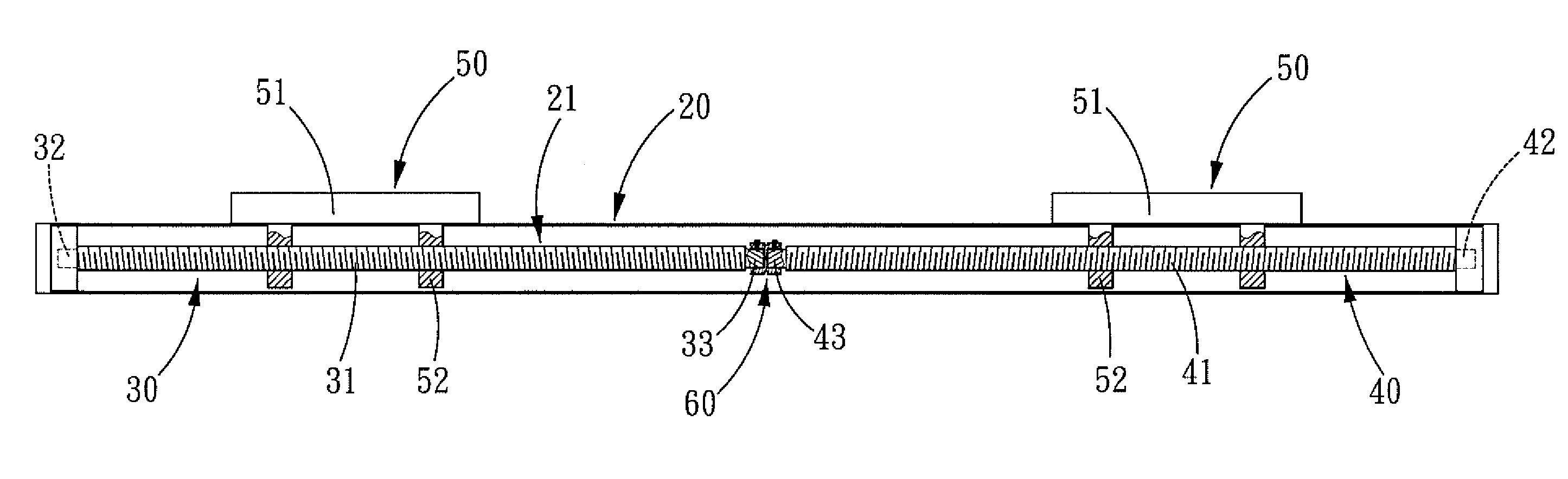
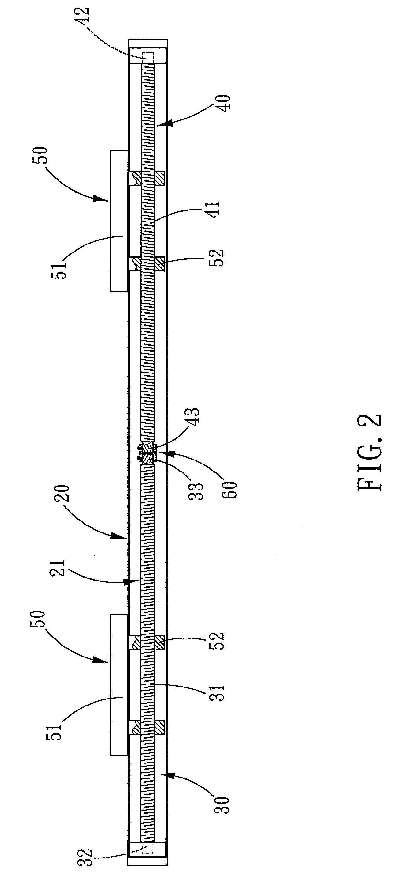
[0024]Referring to FIGS. 2-7, a linear table structure in accordance with the present invention comprises: a groove body 20, a first screw rod 30, a second screw rod 40, two sliding seats 50, a connecting calibrating assembly 60, and an assistant member 70.

[0025]The groove body 20 is interiorly defined with a receiving space 21.

[0026]The first screw 30 is formed on its outer surface with a first threaded section 31, at one end of the first threaded section 31 is axially formed a first pivot portion 32, and at the other end of the first threaded section 31 is axially formed a first connecting portion 33.

[0027]The second screw 40 is formed on its outer surface with a second threaded section 41 whose pitch is the same as the pitch of the first th...


PUM


Abstract

A linear table structure comprises a groove body, a first screw, a second screw, two sliding seats, and a connecting calibrating assembly. One end of the first screw and that of the second screw are connected and supported by the connecting calibrating assembly, and the positioning portion of the connecting calibrating assembly is used to adjust the pitch error generated on the first and second screws by the sliding seats, thus reducing machining time and cost.

Description

BACKGROUND OF THE INVENTION[0001]1. Field of the Invention[0002]The present invention relates to a table structure, and more particularly to a linear table structure.[0003]2. Description of the Prior Art[0004]A conventional double sliding-seat linear table 10 (as shown in FIG. 1) serves as a holding and positioning device and comprises a groove body 11, a screw 12, and two sliding seats 13.[0005]The groove body 11 is defined with a receiving space 111. A first threaded section 121 and a second threaded section 122 are coaxially and symmetrically formed on the outer surface at both ends of the screw 12. Both ends of the screw 12 are pivotally connected to the opposite inner surfaces of the receiving space 111 of the groove body 11. Each of the sliding seats 13 is disposed at its bottom with two nuts 131 through which the sliding seats 13 are fixed to the first and second threaded sections 121 and 122, respectively. The nuts 131 of the sliding seats 13 are meshed with the clockwise th...

Claims


Application Information

Patent Timeline
IPC IPC(8): A47B13/08
CPCH02K7/003H02K16/00H02K7/06
Inventor CHUO, CHIN-HSINGCHOU, CHI-PIN
Owner HIWIN MIKROSYST
Why Eureka
Try Eureka