Parallel connected hts fcl device

a parallel connection and fcl technology, applied in the direction of superconductors/hyperconductors, superconductor devices, electrical apparatus, etc., can solve the problems of limited existing space available to expand capacity, the delivery of power to users via transmission and distribution networks remains significant, and the utility has struggled to meet these increasing demands

Inactive Publication Date: 2008-08-14
AMERICAN SUPERCONDUCTOR
View PDF57 Cites 25 Cited by
  • Summary
  • Abstract
  • Description
  • Claims
  • Application Information

AI Technical Summary

Benefits of technology

[0028]The details of one or more implementations are set forth in the accompanying drawings and the description below. Other features and advantages will become apparent from the description, the drawings, and the claims.

Problems solved by technology

As worldwide electric power demands continue to increase significantly, utilities have struggled to meet these increasing demands both from a power generation standpoint as well as from a power delivery standpoint.
Delivery of power to users via transmission and distribution networks remains a significant challenge to utilities due to the limited capacity of the existing installed transmission and distribution infrastructure, as well as the limited space available to add additional conventional transmission and distribution lines and cables.
This is particularly pertinent in congested urban and metropolitan areas, where there is very limited existing space available to expand capacity.
The design of HTS cables results in significantly lower series impedance, in their superconducting state, when compared to conventional overhead lines and underground cables.
In addition to capacity problems, another significant problem for utilities resulting from increasing power demand (and hence increased levels of power being generated and transferred through the transmission and distribution networks) are increased “fault currents” resulting from “faults”.
Faults may result from network device failures, acts of nature (e.g. lightning), acts of man (e.g. an auto accident breaking a power pole), or any other network problem causing a short circuit to ground or from one phase of the utility network to another phase.
In general, such a fault appears as an extremely large load materializing instantly on the utility network.
The fault currents can be so large in large power grids that without fault current limiting measures, most electrical equipment in the grid may be damaged or destroyed.
Unfortunately, with increased levels of power generation and transmission on utility networks, fault current levels are increasing to the point where they will exceed the capabilities of presently installed or state-of-the-art circuit breaker devices (i.e. be greater than 80,000 amps) both at distribution and transmission level voltages.
Even at lower fault current levels, the costs of upgrading circuit breakers from a lower level to a higher level across an entire grid can be very high.
Unfortunately, such standalone HTS FCLs are currently quite large and expensive.
Utilities may also use large inductors, but they may cause extra losses, voltage regulation and grid stability problems.
And, unfortunately, pyrotechnic current limiters (e.g., fuses) need replacement after every fault event.
Further, while new power electronic FCLs are under development, there are questions about whether they can be fail-safe and whether they can be extended reliably to transmission voltage levels.
To allow HTS cables to survive the flow of fault currents, a significant amount of copper may be introduced in conjunction with the HTS wire, but this adds to the weight and size of the cable.
Nor was the possibility of additional grid elements that could optimize the functionality of the link.

Method used


Image

  • Parallel connected hts fcl device
  • Parallel connected hts fcl device
  • Parallel connected hts fcl device

Examples


Embodiment Construction

Overview

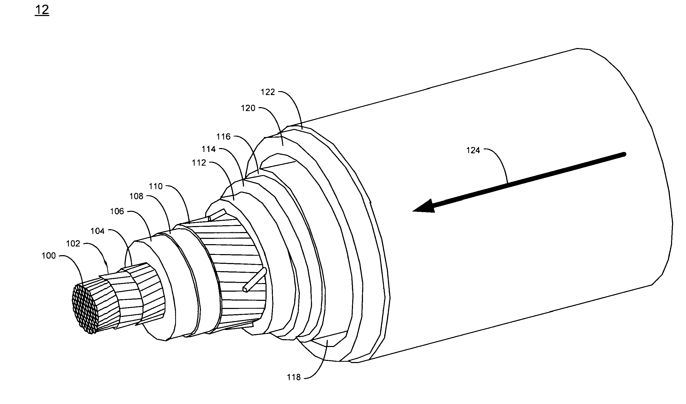
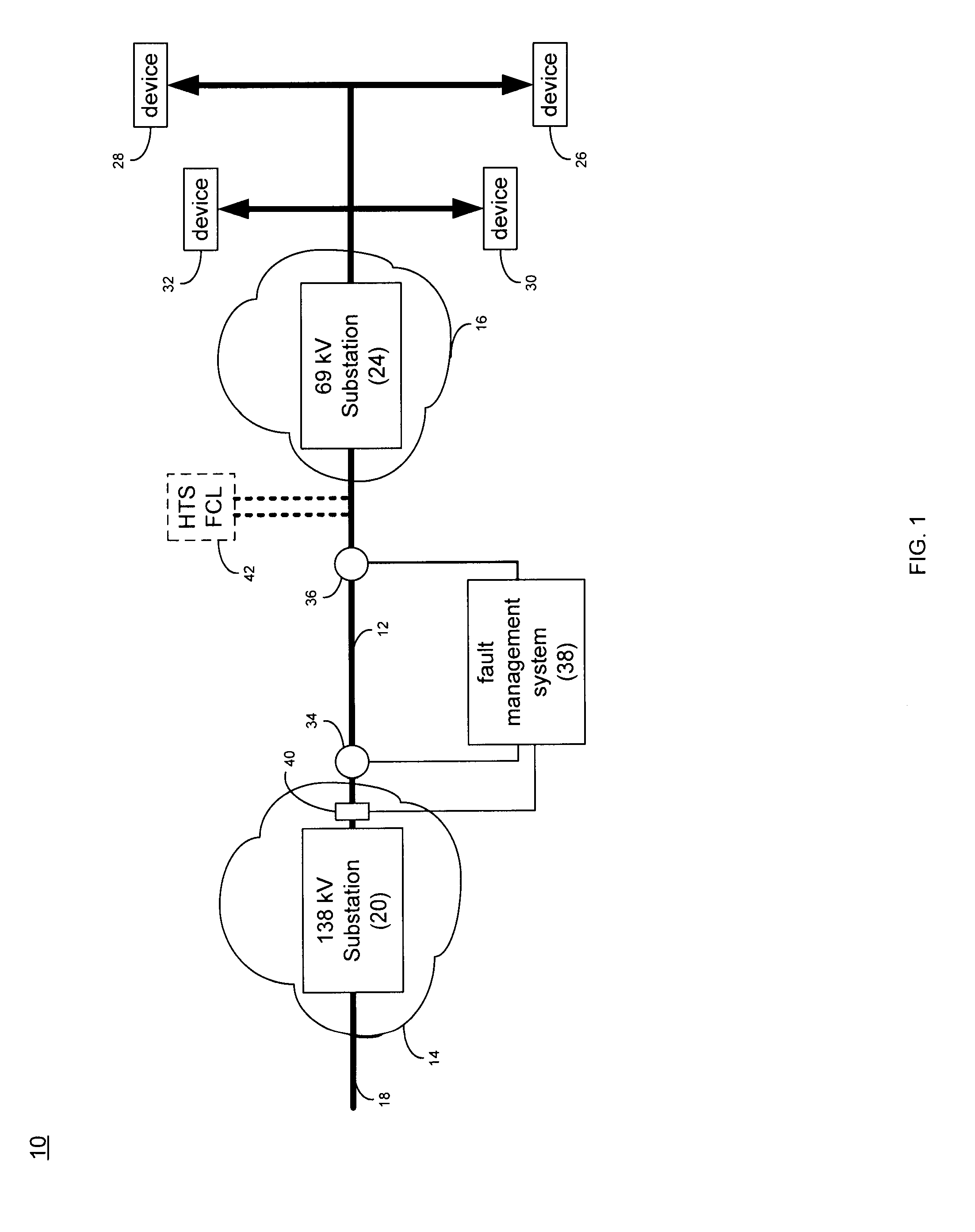
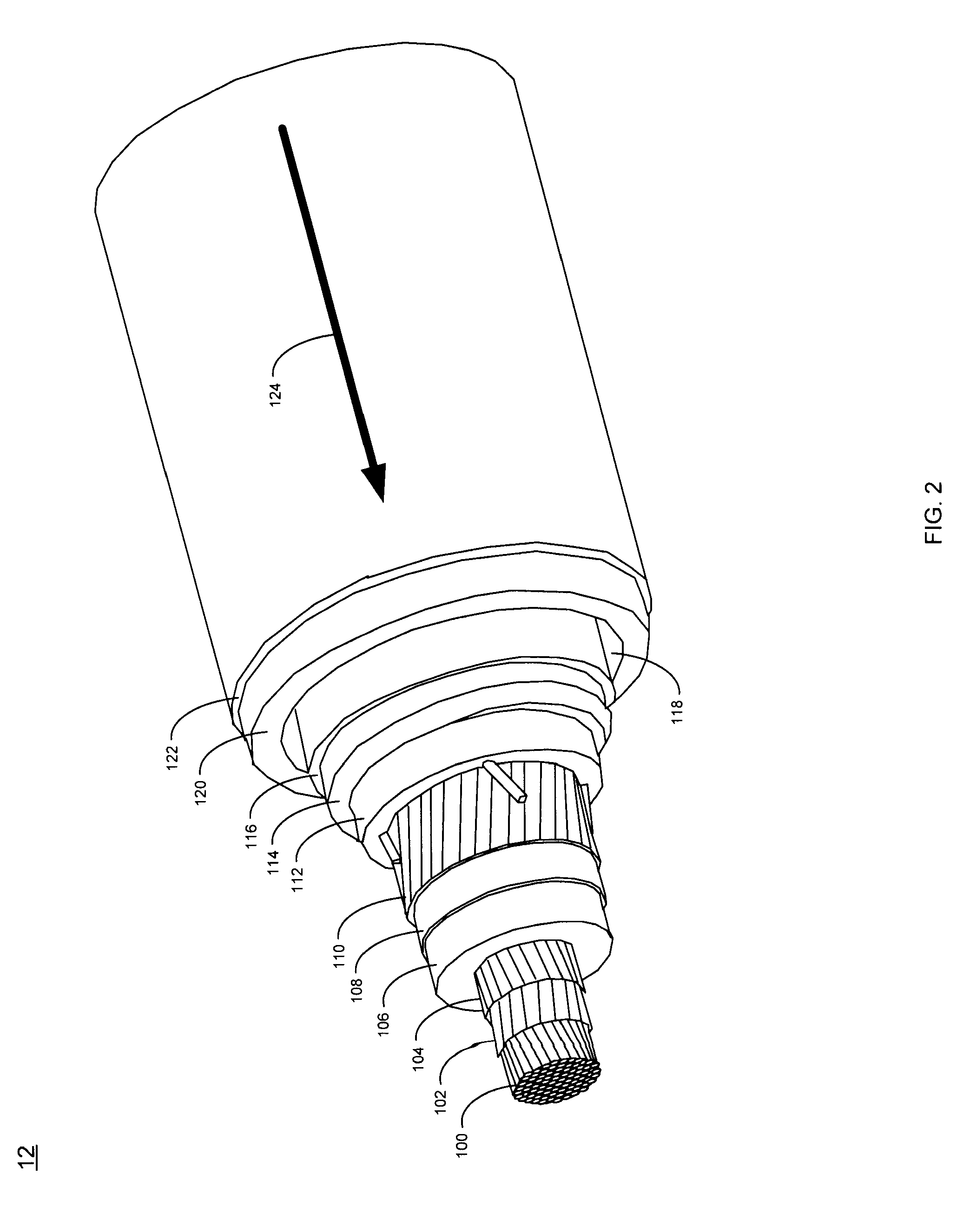
[0042]Referring to FIG. 1, a portion of a utility power grid 10 may include a high temperature superconductor (HTS) cable 12. HTS cable 12 may be hundreds or thousands of meters in length and may provide a relatively high current / low resistance electrical path for the delivery of electrical power from generation stations (not shown) or imported from remote utilities (not shown).

[0043]The cross-sectional area of HTS cable 12 may be only a fraction of the cross-sectional area of a conventional copper core cable and may be capable of carrying the same amount of electrical current. As discussed above, within the same cross-sectional area, an HTS cable may provide three to five times the current-carrying capacity of a conventional AC cable; and up to ten times the current-carrying capacity of a conventional DC cable. As HTS technology matures, these ratios may increase.

[0044]As will be discussed below in greater detail, HTS cable 12 may include HTS wire, which may be capable of h...


PUM

PropertyMeasurementUnit
non-cryogenic temperatureaaaaaaaaaa
temperatureaaaaaaaaaa
total thicknessaaaaaaaaaa

Abstract

A superconducting electrical cable system is configured to be included within a utility power grid having a known fault current level. The superconducting electrical cable system includes a non-superconducting electrical path interconnected between a first node and a second node of the utility power grid. A superconducting electrical path is interconnected between the first node and the second node of the utility power grid. The superconducting electrical path and the non-superconducting electrical path are electrically connected in parallel, and the superconducting electrical path has a lower series impedance than the non-superconducting electrical path when the superconducting electrical path is operated below a critical current level and a critical temperature. The superconducting electrical path is configured to have a series impedance that is at least N times the series impedance of the non-superconducting electrical path when the superconducting electrical path is operated at or above one or more of the critical current level and the superconductor critical temperature. N is greater than 1 and is selected to attenuate, in conjunction with an impedance of the non-superconducting electrical path, the known fault current level by at least 10%.

Description

RELATED APPLICATIONS(S)[0001]This application is a continuation-in-part of and claims priority to U.S. patent application Ser. No.: 11 / 673,281, filed 9 Feb. 2007, and entitled “Parallel Connected HTS Utility Device and Method of Using Same” (H&K Docket No.: 079314.00008 / AMSC811), which is herein incorporated by reference.[0002]This application claims priority to U.S. Patent Application Serial No.: ______, filed 20 Mar. 2007, and entitled “Fault Current Limiting HTS Cable and Method of Configuring Same” (H&K Docket No.: 079314.00010 / AMSC811CIP2), which is herein incorporated by reference.[0003]This application claims priority to U.S. patent application Ser. No.: ______, filed 20 Mar. 2007, and entitled “HTS Wire” (H&K Docket No.: 079314.00011 / AMSC814CIP3), which is herein incorporated by reference.[0004]This application claims priority to U.S. patent application Ser. No.: ______, filed 20 Mar. 2007, and entitled “Parallel HTS Transformer Device” (H&K Docket No.: 079314.00012 / AMSC811C...

Claims


Application Information

Patent Timeline
Patent Type & Authority Applications(United States)
IPC IPC(8): H01B12/00
CPCH01B12/02H01B12/16H01L39/16H02H7/001Y02E40/69Y02E40/641Y02E40/647Y02E40/68H02H9/023Y02E40/60H10N60/30H02H9/02
Inventor FOLTS, DOUGLAS C.MAGUIRE, JAMESYUAN, JIEMALOZEMOFF, ALEXIS P.
Owner AMERICAN SUPERCONDUCTOR
Why Eureka
Try Eureka