Power supply device and storage control device

a power supply device and storage control technology, applied in emergency power supply arrangements, dc source parallel operation, instruments, etc., can solve the problems of increasing the number of parts and stockpiles, increasing the cost of power supply devices, and reducing the productivity of power supply devices

Inactive Publication Date: 2008-08-14
HITACHI LTD
View PDF4 Cites 17 Cited by
  • Summary
  • Abstract
  • Description
  • Claims
  • Application Information

AI Technical Summary

Problems solved by technology

Hence, DC/DC converters with an adequate output performance must be prepared in a number equal to the total number of hard disk drives and the costs of power supply devices increase.
Furthermore, because there is a need to prepare DC/DC converters of the same number as that of hard disk drives, there is an increase in the number of parts and the stockpile number, whereby the productivity of the power supply device is reduced.
As a result, the costs of the power supply device increase and the device size also increases.
Furthermore, according to the first conventional technology, because the respective hard disk drives individually contain a DC/DC converter, when a power fault occurs in the DC/DC converter, the respective hard disk drives cannot be operated.
Hence, the DC/DC converter alone cannot be exchanged.
Furthermore, with t...

Method used


Image

  • Power supply device and storage control device
  • Power supply device and storage control device
  • Power supply device and storage control device

Examples


first embodiment

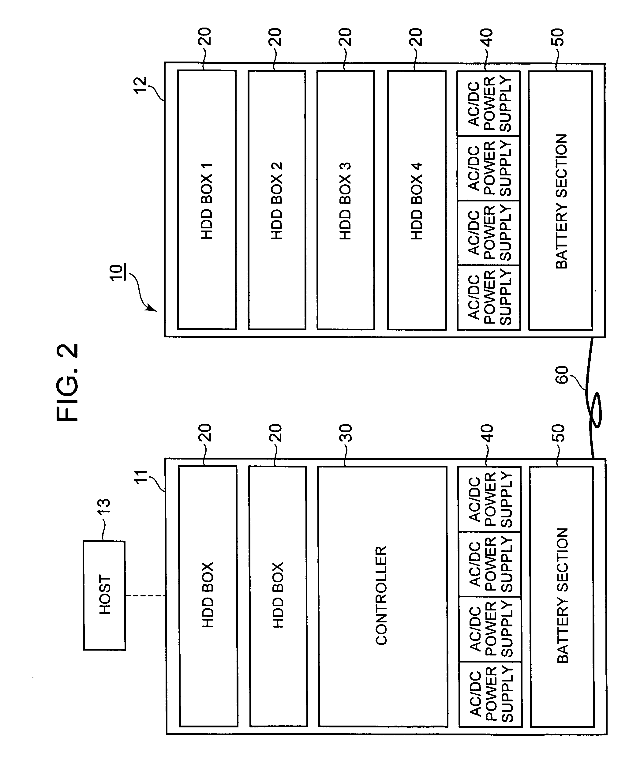
[0094]FIG. 2 is an explanatory diagram that schematically shows the constitution of a storage control device 10. FIG. 2 is represented to resemble a front view but differs from an actual front view.

[0095]The storage control device 10 can be constituted by connecting a basic enclosure 11 and an additional enclosure 12 by means of a cable 60, for example. The storage control device 10 may also be constituted by the basic enclosure 11 alone.

[0096]The basic enclosure 11 provides the basic constitution of the storage control device 10 and the basic functions of the storage control device 10 can be implemented by means of the basic enclosure 11 alone. The basic enclosure 11 is constituted comprising, for example, a plurality of hard disk boxes (‘HDD boxes’ hereinbelow) 20, a controller 30, an AC / DC power supply section 40, and a battery section 50. A host 13 serving as a higher-level device is connected via a communication network to the basic enclosure 11.

[0097]The additional enclosure...

second embodiment

[0229]The second embodiment of the present invention will now be described on the basis of FIGS. 17 to 19. Each of the following respective embodiments including this embodiment correspond to the modified example of the first embodiment.

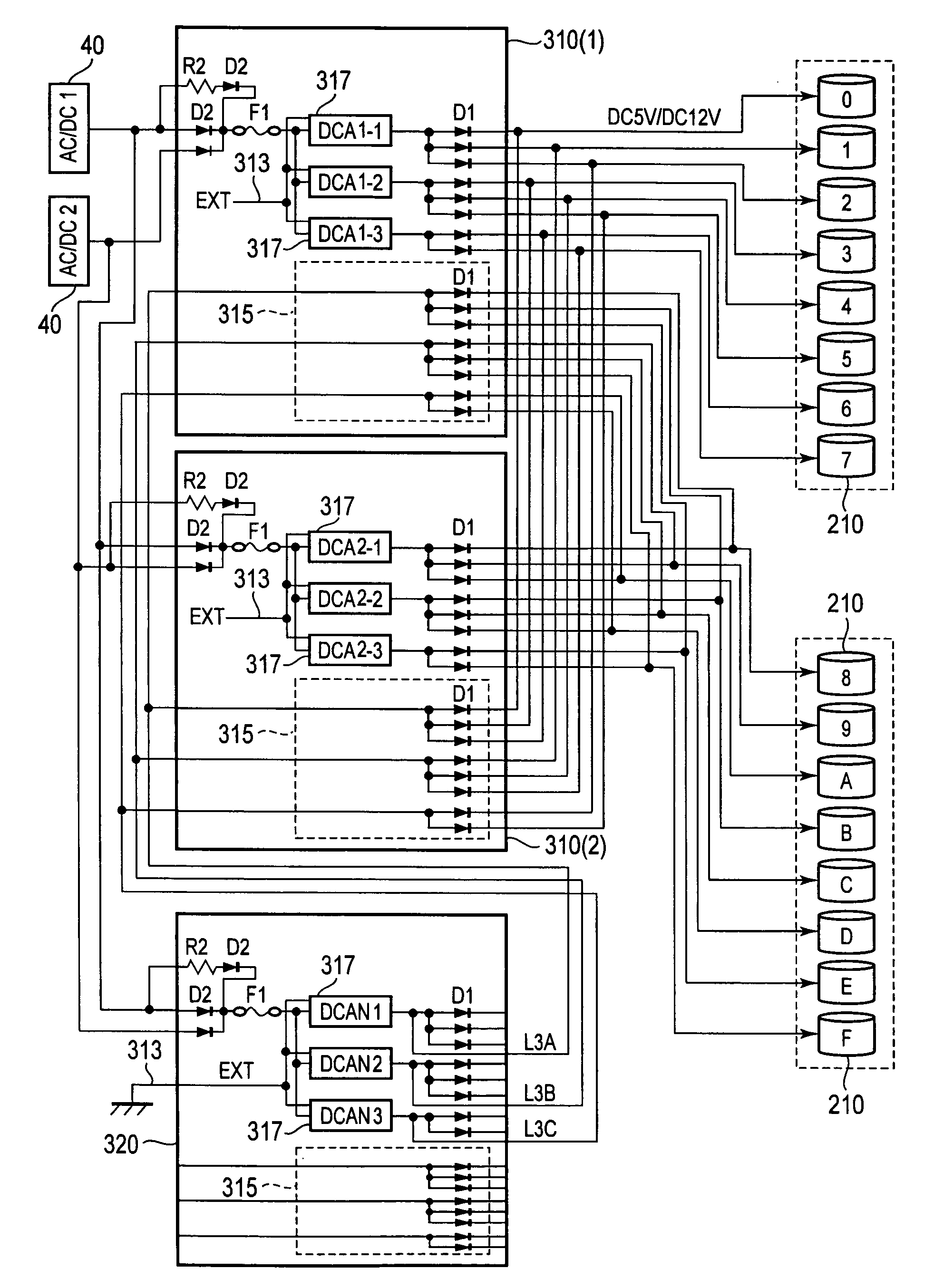
[0230]FIG. 17 is a circuit diagram showing the power supply structure of this embodiment. In this embodiment, the number of diodes D1 that exist on the path from the normal power supply substrate 310 to the disk drive 210 and the number of diodes D1 that exists on the path that extends from the redundant power supply substrate 320 to the disk drive 210 via the relay circuit 315 are equal; only the value of the output voltage of the redundant power supply substrate 320 is reduced.

[0231]FIG. 18 is a circuit that focuses on the redundant power supply substrate 320 in FIG. 17. As shown in FIGS. 17 and 18, the paths L3A, L3B, and L3C that connect the respective DC / DC converter 311 and the relay circuit 315 in the redundant power supply substrate 320 are...

third embodiment

[0235]The third embodiment will now be described on the basis of FIGS. 20 and 21. In this embodiment, the output of the DC / DC converter 312 for supplying DC 12V to the respective disk drive 210 is used as the input of the DC / DC converter 311 for supplying DC 5V to the respective disk drives 210.

[0236]In each of the aforementioned embodiments, the respective DC / DC converters 311 convert the DC power input from the AC / DC power supply section 40 into DC 5V and output DC 5V power. In contrast, in this embodiment, the output from the DC / DC converter 312 is input to the respective DC / DC converters 311. The respective DC / DC converters 311 convert DC 12V input from the DC / DC converter 312 into DC 5V and output DC 5V power.

[0237]Therefore, in this embodiment, the respective AC / DC power supply sections 40 are connected to only the DC / DC converter 312. The constitution of the connection between the respective AC / DC power supply sections 40 and the DC / DC converter 312 is...


PUM


Abstract

The power supply device of the present invention supplies power individually to a plurality of disk drives by rendering a plurality of DC/DC converters redundant. One redundant power supply substrate is assigned to a plurality of normal power supply substrates. One redundant power supply substrate supports the outputs of a plurality of normal power supply substrates. The main DC/DC converters in the normal power supply substrate correspond with the subgroups on a one-for-one basis. The secondary DC/DC converters in the redundant power supply substrate each correspond with all of the respective subgroups and are able to supply power to a predetermined single disk drive among the respective disk drives in the subgroups for each of the subgroups.

Description

CROSS-REFERENCE TO RELATED APPLICATIONS[0001]This application relates to and claims priority from Japanese Patent Application No. 2007-28778 filed on Feb. 8, 2007, the entire disclosure of which is incorporated herein by reference.BACKGROUND OF THE INVENTION[0002]1. Field of the Invention[0003]The present invention relates to a power supply device and a storage control device.[0004]2. Description of the Related Art[0005]The storage control device comprises a storage section in which a multiplicity of hard disk drives are connected in the form of an array and provides a host computer (‘host’ hereinbelow) such as a server with logical storage regions (logical volumes).[0006]In order to increase reliability and highly availability, the storage control device provides the host with storage regions that are redundant based on RAID (Redundant Array of Independent Disks). Further, the storage control device affords the various resources such as the microprocessor and communication path red...

Claims


Application Information

Patent Timeline
IPC IPC(8): H02J9/00
CPCG06F1/263H02J1/102G06F1/30H02J1/001
Inventor SUZUKI, HIROSHIINOUE, TETSUYASONE, MASAHIRONAGAMORI, TOSHIYUKIKUROKAWA, MASATERU
Owner HITACHI LTD
Why Eureka
Try Eureka