Portable Communication Device Antenna Arrangement

a communication device and portable technology, applied in the direction of antenna details, non-resonant long antennas, antennas, etc., can solve the problems of affecting the efficiency of portable communication devices, affecting the user's body, so as to achieve the effect of superior internal antennas

Inactive Publication Date: 2008-08-14
SONY ERICSSON MOBILE COMM AB
View PDF15 Cites 0 Cited by
  • Summary
  • Abstract
  • Description
  • Claims
  • Application Information

AI Technical Summary

Benefits of technology

[0016]Implementations of the present invention may enable the provision of a superior internal antenna in a compact portable communication device.

Problems solved by technology

As such, the efficiency of an antenna that is positioned close to the user's body may be diminished to an unacceptable level.
However, such portable communication devices may not only be designed to be worn as attached to the body, but to be worn alternatively loosely relative to the body, such as hanging on a lanyard that the may be draped around the neck of the user.
When the portable communication device, in the course of being moved while worn, assumes a contrary orientation relative to the antenna, radio signals may be directed toward the user's body and thereby obstructed.
A communication with the host communication device may adversely affected or entirely attenuated.
Accordingly, with respect to devices that are small and may be worn so as to assume random orientations, directional antennas may be subject to diminished performance.

Method used


Image

  • Portable Communication Device Antenna Arrangement
  • Portable Communication Device Antenna Arrangement
  • Portable Communication Device Antenna Arrangement

Examples


Embodiment Construction

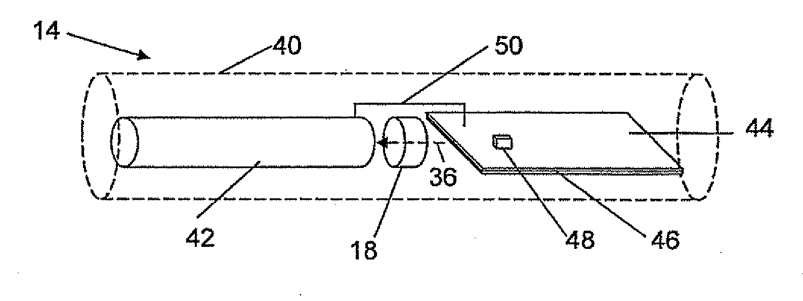
[0050]FIG. 1 schematically shows a user 10 wearing a first communication device 14. First communication device 14 may be worn loosely relative to the body of user 10, for example, through being disposed on a string or lanyard 12 that hangs from the neck of user 10. Alternatively, first communication device 14 may fasten to user 10 with a type of fastener, such as a clip. First communication device 14 may be configured to communicate with a second communication device 16, as well as to other devices (not shown).

[0051]Communication between first and second communication devices 14 and 16 may be enabled, for example, using a suitable short-range communication technique, which according to various implementations of the present invention, may include Bluetooth™ technology. The invention is however not limited to Bluetooth™, but can use other suitable communication techniques and communication bands, for instance the UWB (ultra wide band) frequency range. The invention is not limited to ...


PUM


Abstract

A portable communication device is provided, which includes a radio communication unit, an antenna exciter element for connection to the radio communication unit and ground and at least one further antenna element provided on one side of the antenna exciter element. The further antenna elements comprise a first mass block of electrically conducting material including components provided for the operation of the portable communication device. The mass block is dimensioned for operating in a frequency band in which communication is desired when being excited by the antenna exciter element and each mass block and the antenna exciter element extend in three dimensions.

Description

RELATED APPLICATION[0001]This application claims priority under 35 U.S.C. § 119 based on U.S. Provisional Application Ser. No. 60 / 887,913, filed Feb. 2, 2007, the disclosure of which is incorporated herein by reference.TECHNICAL FIELD OF THE INVENTION[0002]The present invention relates to antennas for communication devices and, more particularly, to a communication device in which mass blocks and an exciter are used for providing an antenna.DESCRIPTION OF RELATED ART[0003]Portable communication devices (e.g., headphones) that are provided as accessories to a “host” portable communication device, such as a mobile phone, may be configured to communicate with the host portable communication device via a wireless connection. A variety of wireless communication technologies exists, which includes the widely-popular Bluetooth™ technology. However, other radio standards and wireless communication protocols exist, such as UWB (ultra wide band).[0004]The dimensions of antenna arrangements to...

Claims


Application Information

Patent Timeline
Patent Type & Authority Applications(United States)
IPC IPC(8): H01Q1/24
CPCH01Q1/243H01Q11/08H01Q7/00H01Q1/362
Inventor ZWEER, JAN-WILLEMHUPKES, EMST
Owner SONY ERICSSON MOBILE COMM AB
Why Eureka
Try Eureka