Supercharge Your Innovation With Domain-Expert AI Agents!

Screw Rotor and Screw Fluid Machine

a screw fluid machine and screw rotor technology, which is applied in the direction of mechanical equipment, machines/engines, liquid fuel engines, etc., can solve the problems of large amount of discharge gas to be transferred through, unavoidable meshing phase where the screw rotors are interfering with each other, and inability to meshed to each other

Inactive Publication Date: 2008-08-14
NABLESCO CORP
View PDF7 Cites 4 Cited by
  • Summary
  • Abstract
  • Description
  • Claims
  • Application Information

AI Technical Summary

Benefits of technology

The present invention provides a screw type dry vacuum pump with a screw rotor and screw fluid machine that can suppress the amount of gas leakage and improve the discharge rate of the gas. The invention solves the problem of a large amount of gas leakage and reversal during the transfer process by keeping the gap between the screw rotors constant. The screw rotor has a cross-sectional shape with an arc forming a deddendum portion, which is connected smoothly with the outer circumferential portion and the other section equally divided into two. The predetermined curve portions are formed by a combination of an arc and a straight line, which can be connected smoothly with the deddendum portion and the outer circumferential portion. The invention provides a screw type fluid machine with a simplified manufacturing process and improved discharge rate of the gas.

Problems solved by technology

In tooth profiles formed by such curves, a meshing phase where the screw rotors are interfered with each other is unavoidably created during the rotation of the screw rotors.
Therefore, it is not possible that the screw rotors are meshed to each other with no gap or with a constant gap over all meshing phases.
Accordingly, there has been a problem that a large amount of discharge gas to be transferred could be leaked through the large gap that is formed between the screw rotors in a part of the meshing phases according to the rotation of the screw rotors.
As a result, a considerable amount of the discharge gas could be reversed toward a discharging chamber, and it is therefore difficult to improve discharge rate of the discharge gas in such a conventional screw type dry vacuum pump.

Method used


Image

  • Screw Rotor and Screw Fluid Machine
  • Screw Rotor and Screw Fluid Machine
  • Screw Rotor and Screw Fluid Machine

Examples


Embodiment Construction

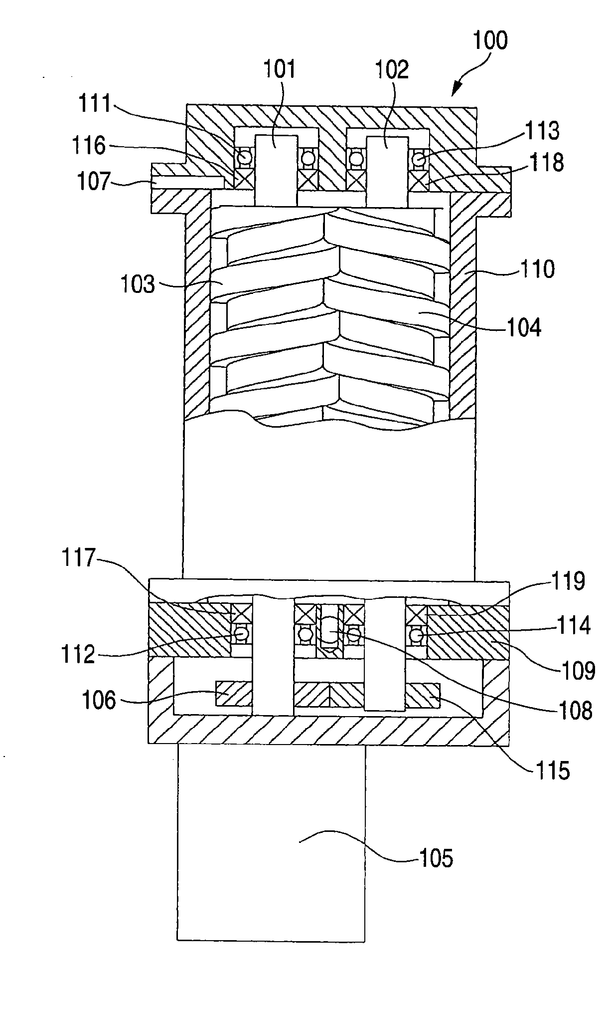
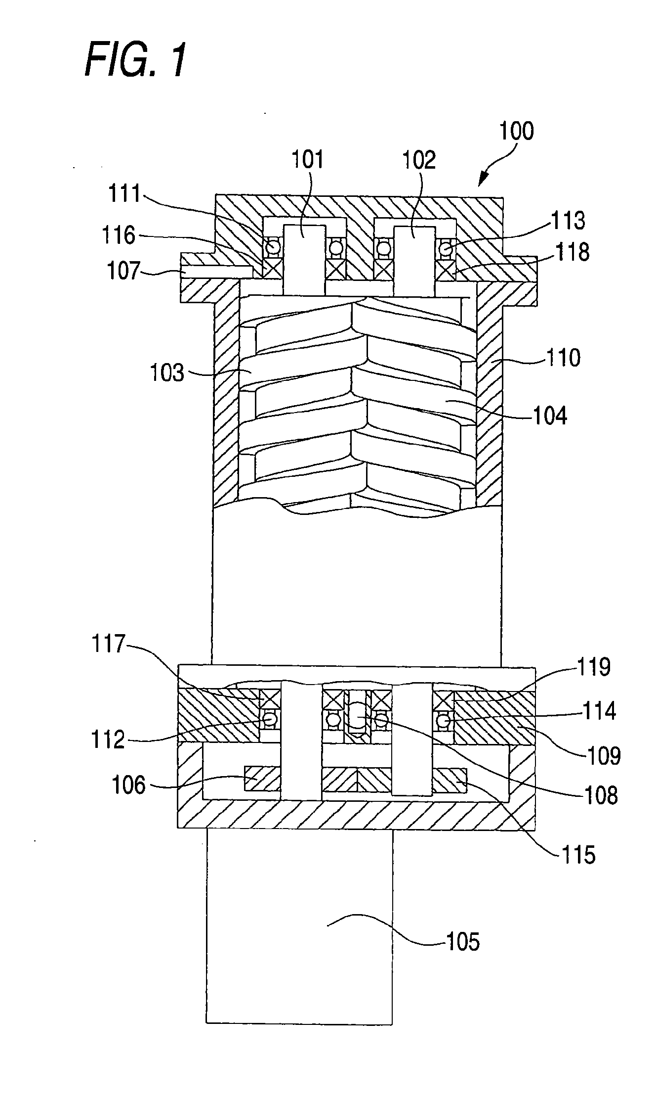
[0034]FIG. 1 shows an embodiment of a screw type dry vacuum pump 100 in which screw rotors according to the invention are employed.

[0035]The screw type dry vacuum pump 100, as shown in FIG. 1, are provided with two shafts 101,102 supported in a casing 110 through bearings 111,112,113,114. Screw rotors 103, 104 having screw grooves are provided on the shafts 101, 102. One shaft 101 is driven by a motor 105 and this rotation is transmitted through a timing gear 106 attached to the shaft 101 by meshing with the a timing gear 115 attached to the other shaft 102. That is, the screw rotors 103, 104 are rotated in synchronism with each other by means of the timing gears 106,115. The casing 110 is provided with a suction port 107 for introducing a discharge gas in a discharging chamber therefrom and a discharge port 108 for discharging the exhaust gas in a discharging chamber that is transferred from a side of the suction port 107. By the above construction, the screw rotors 103, 104 are ro...


PUM


Abstract

The object of the invention is to provide a screw type fluid machine in which leak of gas is kept in constant, in other words, in which a gap between the screw rotors is kept substantially in constant in a discharging chamber during operation. In a screw type fluid machine, screw rotor having a cross-sectional shape (805) of a tooth profile with respect to an axial direction thereof includes an arc (1) forming a deddendum portion, and an arc (3) forming an outer circumferential portion, wherein one (5) of two curves connecting the outer circumferential portion and the deddendum portion is defined by a trochoid curve created based on a point on an outer circumference of a mating screw rotor and the other of these two curves, which is divided equally into two sections constituted by a section between a pitch circle and the outer circumferential portion and a section between the pitch circle and the deddendum portion, is defined by a predetermined curve for one (7) of the sections and a fitting curve for the other (9) of the sections that is created so as to correspond to the predetermined curve for the one of the sections divided equally into two in the mating screw rotor during meshing.

Description

CROSS-REFERENCE TO RELATED APPLICATIONS[0001]This application is a Section 371 of International Application No. PCT / JP2005 / 009415, filed May 24, 2005, which was published in the Japanese language on Dec. 1, 2005, under International Publication No. WO / 2005 / 113984 and the disclosure of which is incorporated herein in its entirety by reference.BACKGROUND OF THE INVENTION[0002]This invention relates to a screw rotor in a screw fluid machine such as screw type compressor, screw type vacuum pump and screw type extension machine. The invention particularly relates to a profile curve of the screw rotor.[0003]Conventionally, as a screw fluid machine (hereinafter, a screw type dry vacuum pump is described as an example.), there has been known a screw type dry vacuum pump in which a pair of screw rotors are mounted in a housing through bearings and one of the screw rotors is driven by a motor such that the screw rotors are rotated without interfere therebetween by meshing one timing gear atta...

Claims


Application Information

Patent Timeline
Patent Type & Authority Applications(United States)
IPC IPC(8): F01C1/18F01C1/08F04C18/16F04C25/02
CPCF04C18/16F01C1/084F04C25/02
Inventor NACHI, TSUYOSHI
Owner NABLESCO CORP
Features
  • R&D
  • Intellectual Property
  • Life Sciences
  • Materials
  • Tech Scout
  • Unparalleled Data Quality
  • Higher Quality Content
  • 60% Fewer Hallucinations
Learn More