Redirect Recovery Cache

Active Publication Date: 2008-08-14
MEDIATEK INC
View PDF1 Cites 65 Cited by
  • Summary
  • Abstract
  • Description
  • Claims
  • Application Information

AI Technical Summary

Benefits of technology

[0008]In another embodiment, a redirect recovery cache comprises a plurality of cache entries and a control unit coupled to the cache entries. Each cache entry is tagged with a redirect address and a corresponding branch history, and is configured to store operations corresponding to instructions fetched in response to respective mispredicted branch operations. The control unit is coupled to receive a redirect address and a redirect branch history for a detected mispredicted branch operation. The control unit is configured to detect a partial hit in a hit cache entry of the plurality of entries if the redirect address matches the tag but the redirect branch history does not match the tag, and to detect a full hit if the redirect address and the redirect branch history matches the tag.
[0009]In an embodiment, a method comprises detecting a mispredicted branch operation; transmitting a redirect address to a redirect recovery cache and to a fetch control unit in response to detecting the mispredicted branch operation, wherein the redirect address identifies a correct target of the branch operation; detecting a hit in the redirect recovery cache; and supplying one or more operations from the hit entry of the redirect recovery cache to a processor pipeline, bypassing at least one stage of the pipeline.
[0010]In one embodiment, the redirect recovery cache is a secondary source of instruction operations, and the main instruction fetch pipeline is still used the majority of the time. The redirect recovery cache may supply instruction operations to cover one or more early pipeline stages in the event of a redirect (where redirects are likely infrequent because of highly a

Problems solved by technology

While the high operating frequencies of deeply pipelined processors can improve overall performance, deep pipelines also present various challenges to a successful design.
For example, branch instructions are such a challenge.
The instructions from the correct target can then be fetched, but performance has been lost in the interim.
For deep pipelines, this performance loss can be especially severe.
Accordingly,

Method used


Image

  • Redirect Recovery Cache
  • Redirect Recovery Cache
  • Redirect Recovery Cache

Examples


Example

[0016]While the invention is susceptible to various modifications and alternative forms, specific embodiments thereof are shown by way of example in the drawings and will herein be described in detail. It should be understood, however, that the drawings and detailed description thereto are not intended to limit the invention to the particular form disclosed, but on the contrary, the intention is to cover all modifications, equivalents and alternatives falling within the spirit and scope of the present invention as defined by the appended claims.

DETAILED DESCRIPTION OF EMBODIMENTS

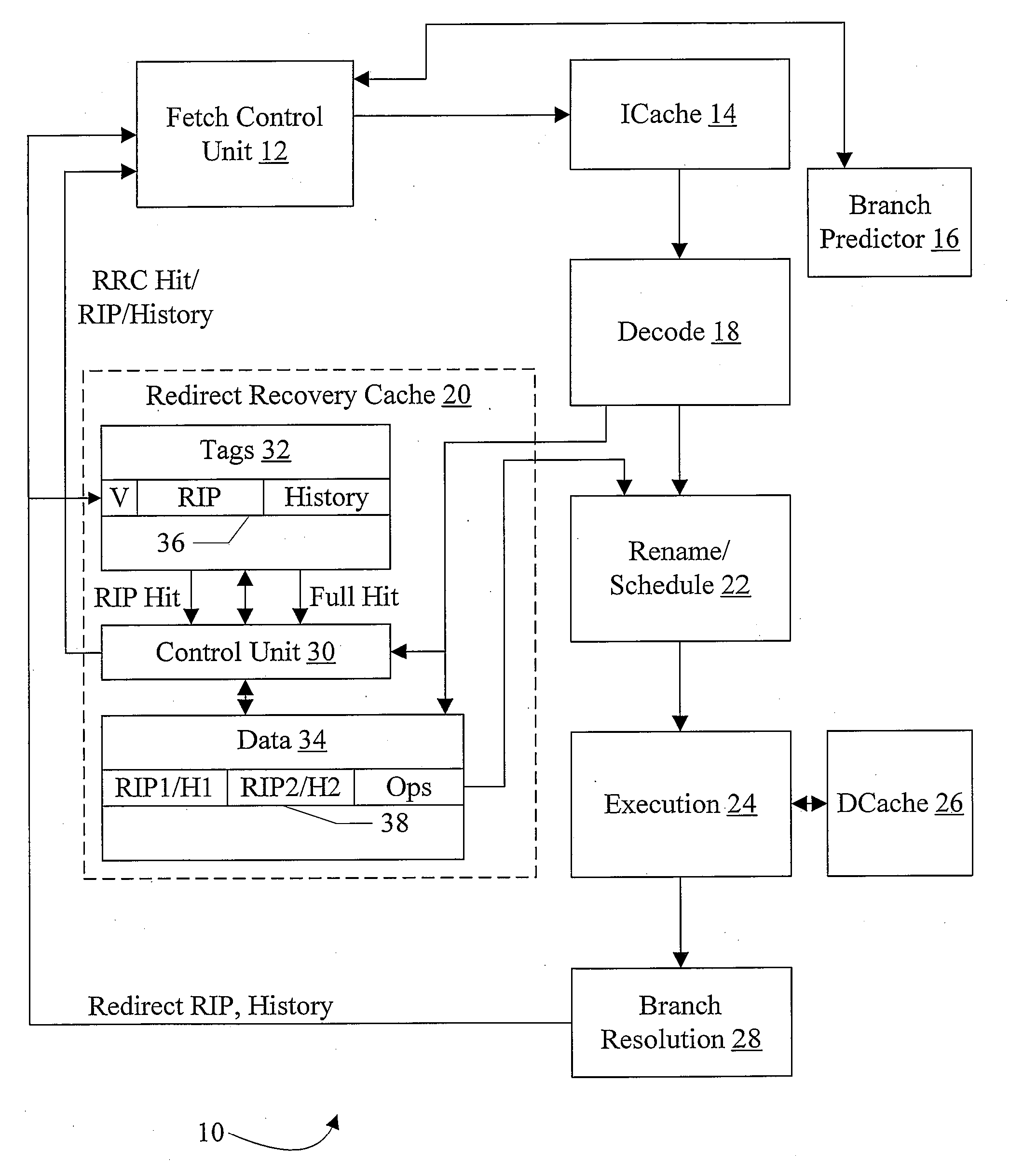
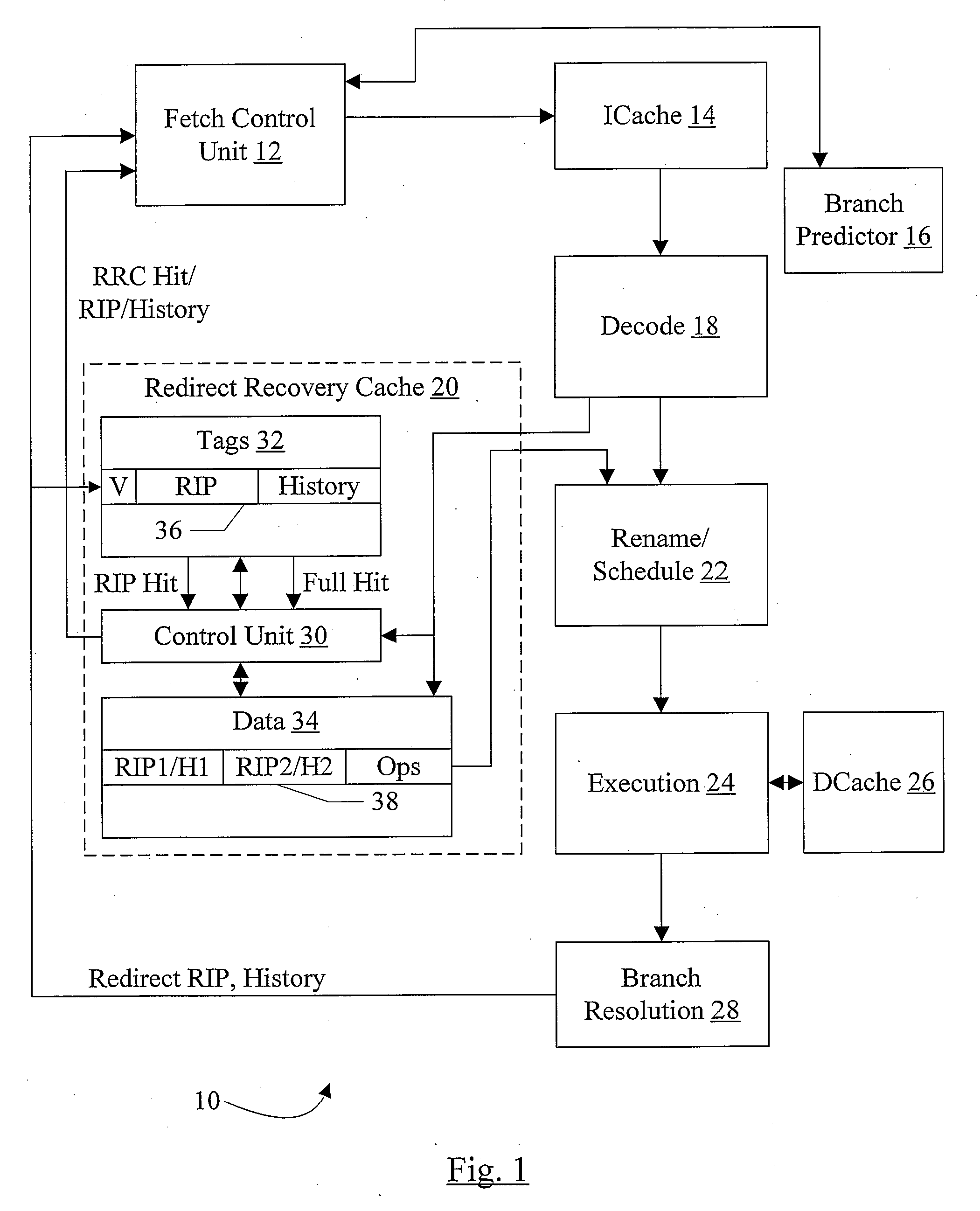
[0017]Turning now to FIG. 1, a block diagram of one embodiment of a processor 10 is shown. In the illustrated embodiment, the processor 10 comprises a fetch control unit 12, an instruction cache (ICache) 14, a branch predictor 16, a decode unit 18, a redirect recovery cache 20, a rename / schedule unit 22, an execution unit 24, a data cache (DCache) 26, and a branch resolution unit 28. The fetch control unit 1...


PUM


Abstract

In one embodiment, a processor comprises a branch resolution unit and a redirect recovery cache. The branch resolution unit is configured to detect a mispredicted branch operation, and to transmit a redirect address for fetching instructions from a correct target of the branch operation responsive to detecting the mispredicted branch operation. The redirect recovery cache comprises a plurality of cache entries, each cache entry configured to store operations corresponding to instructions fetched in response to respective mispredicted branch operations. The redirect recovery cache is coupled to receive the redirect address and, if the redirect address is a hit in the redirect recovery cache, the redirect recovery cache is configured to supply operations from the hit cache entry to a pipeline of the processor, bypassing at least one initial pipeline stage.

Description

BACKGROUND[0001]1. Field of the Invention[0002]This invention is related to the field of processors and, more particularly, to branch instruction processing in processors.[0003]2. Description of the Related Art[0004]Over time, processors have been produced with increased operating frequencies. Reaching the operating frequencies of modem processors has been accomplished, at least in part, using deeper instruction processing pipelines. Generally, a pipeline is designed by dividing the work to be performed (e.g. instruction processing, in this case) into multiple portions, each of which is assigned to a given pipeline stage. Instructions pass from stage to stage in the pipeline. Pipeline stages can operate on different instructions in parallel, thus overlapping the processing of instructions in time. Deep pipelines have many such stages. For example, pipelines having 10 pipeline stages, 15 pipeline stages, or even more are often found in modem processors. A pipeline having 10 stages ca...

Claims


Application Information

Patent Timeline
IPC IPC(8): G06F9/312
CPCG06F9/3808G06F9/3861G06F9/3844
Inventor SHEN, GENE W.LIE, SEAN
Owner MEDIATEK INC
Why Eureka
Try Eureka