Method and Apparatus for Channel Change in Dsl System

a channel change and channel technology, applied in the field of digital subscriber line (dsl) systems, can solve problems such as buffer overflow/underflow at the decoder, lower quality video during a transitional period, and encoder rate control

Inactive Publication Date: 2008-08-14
THOMSON RES FUNDING
View PDF22 Cites 28 Cited by
  • Summary
  • Abstract
  • Description
  • Claims
  • Application Information

AI Technical Summary

Benefits of technology

[0027]According to still another aspect of the present invention, there is provided, in a set top box (STB) connected to a Digital Subscriber Line (DSL) system and a display device, a method for supporting a picture-in-picture (PIP) mode on the display device. The method includes the step of decoding, using a standard resolution decoder, a normal stream picture of a normal stream for display on the display device in the PIP mode. The method further includes the step of decoding, using a low resolution decoder, a low resolution picture of a parallel coded stream for display on the display device in the PIP mode.

Problems solved by technology

When a receiver initially begins receiving a program on a particular channel, following a channel change or upon the initial turning on of the receiver, the receiver must wait until an I picture is received to begin decoding properly, which causes a delay.
This may cause problems with encoder rate control and buffer overflow / underflow at the decoder and the DSLAM.
This problem can be avoided by limiting the size of the channel change stream coded pictures, which leads to lower quality video during a transitional period following a channel change.

Method used


Image

  • Method and Apparatus for Channel Change in Dsl System
  • Method and Apparatus for Channel Change in Dsl System
  • Method and Apparatus for Channel Change in Dsl System

Examples


Embodiment Construction

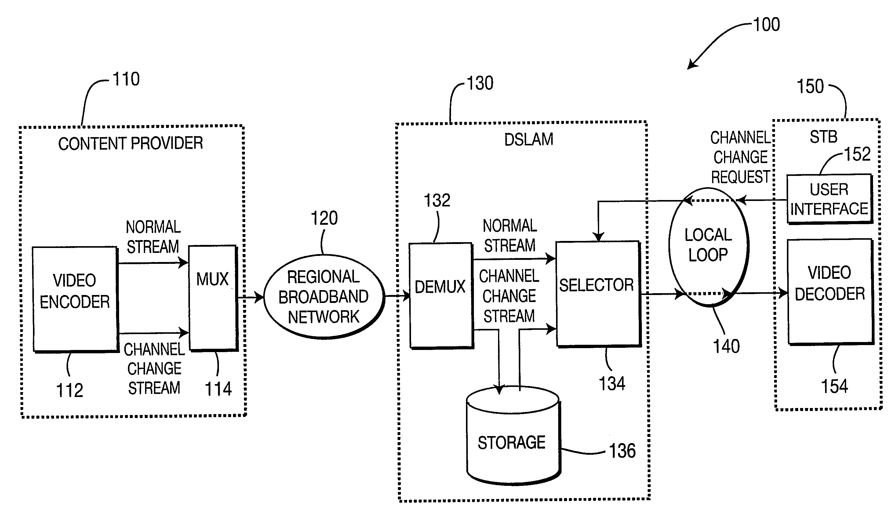
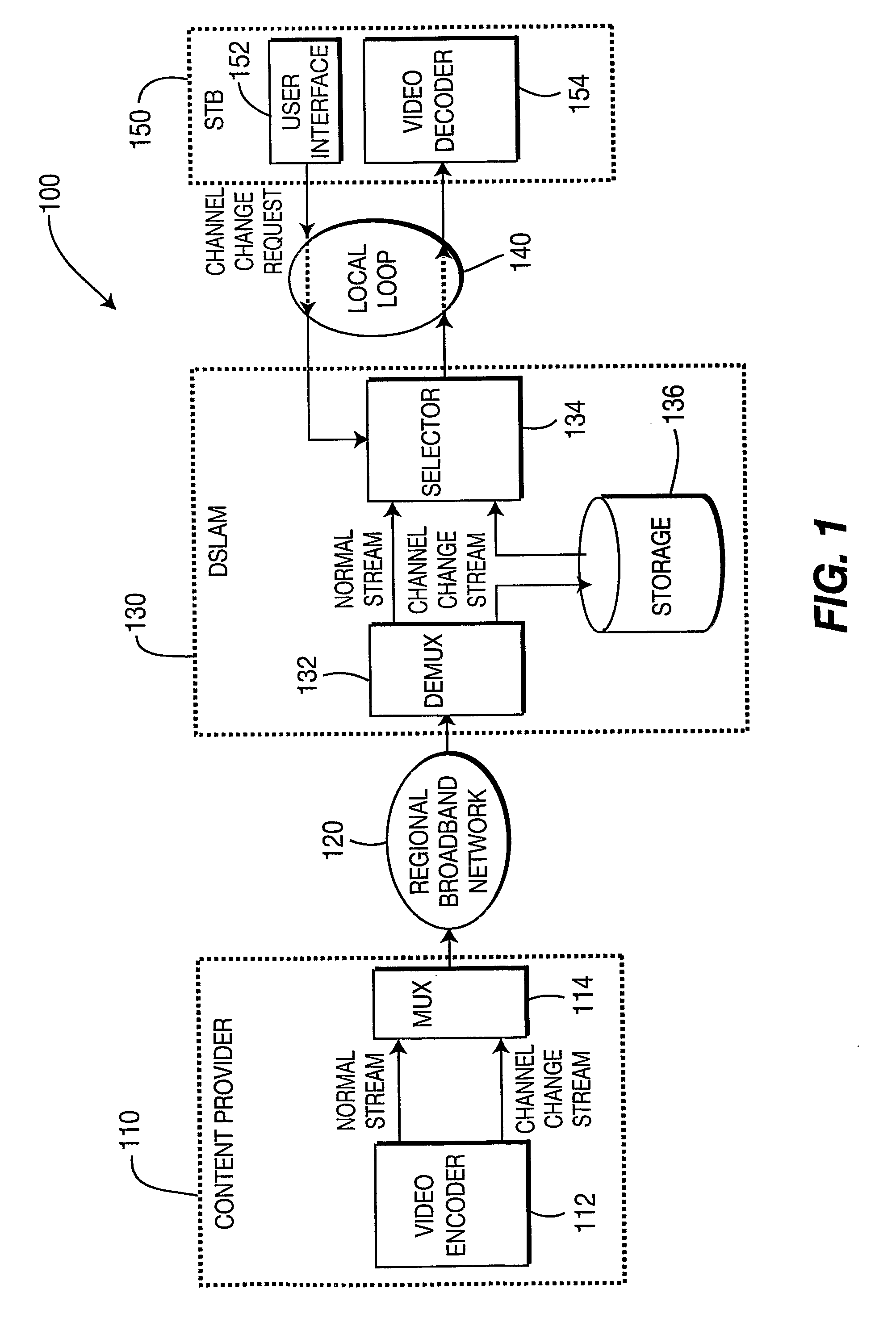
[0035]The present invention is directed to a method and apparatus for changing a channel in a Digital Subscriber Line (DSL) system. In an embodiment of the present invention, the present invention advantageously allows for limiting the channel change delay (change time) in a video over DSL multicast system while improving coding efficiency, with minimal impact on a Digital Subscriber Line Access Multiplexer (DSLAM) that supports Internet Protocol (IP) multicast.

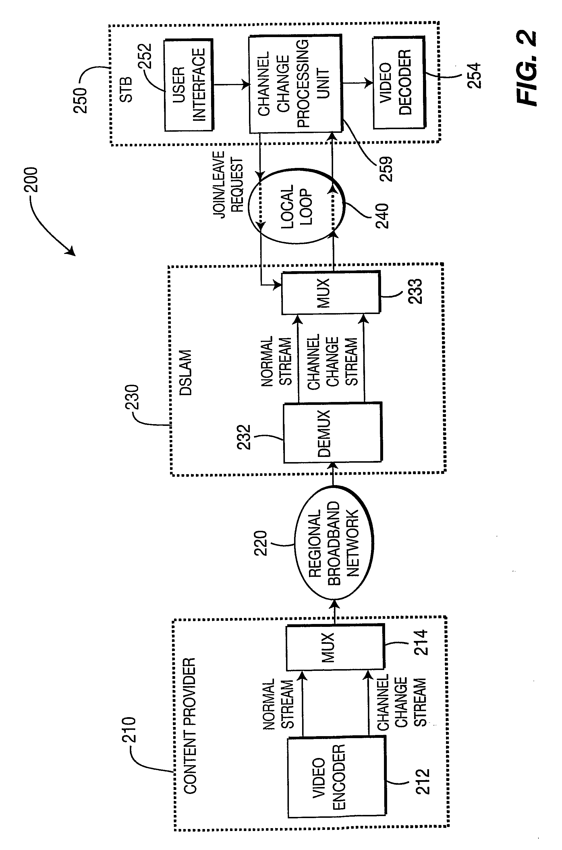
[0036]In accordance with the principles of the present invention, for each program, a relatively low bitrate, low resolution channel change stream is encoded, in addition to the normal coded stream. When a channel change request is received at the set-top box (STB), join requests are made to both the channel change stream and the normal stream of the newly selected program. The channel change stream may also be used for picture-in-picture (PIP) support at the STB, as described further herein below.

[0037]The present descriptio...


PUM


Abstract

There is provided a set top box and corresponding methods for enabling a channel change in a Digital Subscriber Line (DSL) system. The set top box includes a channel change processing unit for sending a join request for both a normal stream and channel change stream upon receiving a channel change request.

Description

CROSS-REFERENCE TO RELATED APPLICATIONS[0001]This application claims the benefit of U.S. Provisional Application Ser. No. 60 / 630,147, filed on Nov. 22, 2004 and entitled “METHOD AND APPARATUS FOR CHANNEL CHANGE IN DSL SYSTEM,” which is incorporated by reference herein in its entirety.FIELD OF THE INVENTION[0002]The present invention generally relates to Digital Subscriber Line (DSL) systems and, more particularly, to a method and apparatus for enabling a channel change in a DSL system.BACKGROUND OF THE INVENTION[0003]In a Digital Subscriber Line (DSL) multicast / broadcast video system, Internet Protocol (IP) multicast is used to transmit compressed video to a set-top box (STB). The Internet Group Management Protocol (IGMP) can be used to select which channel to watch, by sending a join request for the desired channel to a Digital Subscriber Line Access Multiplexer (DSLAM). When that channel is no longer desired, a leave request can be sent to the DSLAM.[0004]In a commercial video ove...

Claims


Application Information

Patent Timeline
Patent Type & Authority Applications(United States)
IPC IPC(8): H04N5/45
CPCH04N5/4401H04N5/45H04N7/17318H04N21/23106H04N21/23439H04N21/6405H04N21/4347H04N21/4383H04N21/4384H04N21/4622H04N21/47202H04N21/2365H04N21/426
Inventor BOYCE, JILL MACDONALD
Owner THOMSON RES FUNDING
Why Eureka
Try Eureka