Cable cleat system

a cable and cable technology, applied in the field of cable cleat system, can solve the problems of difficult adjustment, insufficient simple attachment of window units to the front of the house, and a large latter to perform the adjustment, and achieve the effect of easy micro-adjustmen

Active Publication Date: 2008-08-21
DEUT BANK AG NEW YORK BRANCH AS COLLATERAL AGENT
View PDF64 Cites 4 Cited by
  • Summary
  • Abstract
  • Description
  • Claims
  • Application Information

AI Technical Summary

Benefits of technology

[0010]In accordance with an embodiment of the present invention, a system for adjusting the length and tension of a cable that is used to support ...

Problems solved by technology

Merely attaching the window units to the front of the house is not usually enough.
There is a disadvantage of the typica...

Method used


Image

  • Cable cleat system
  • Cable cleat system
  • Cable cleat system

Examples


Embodiment Construction

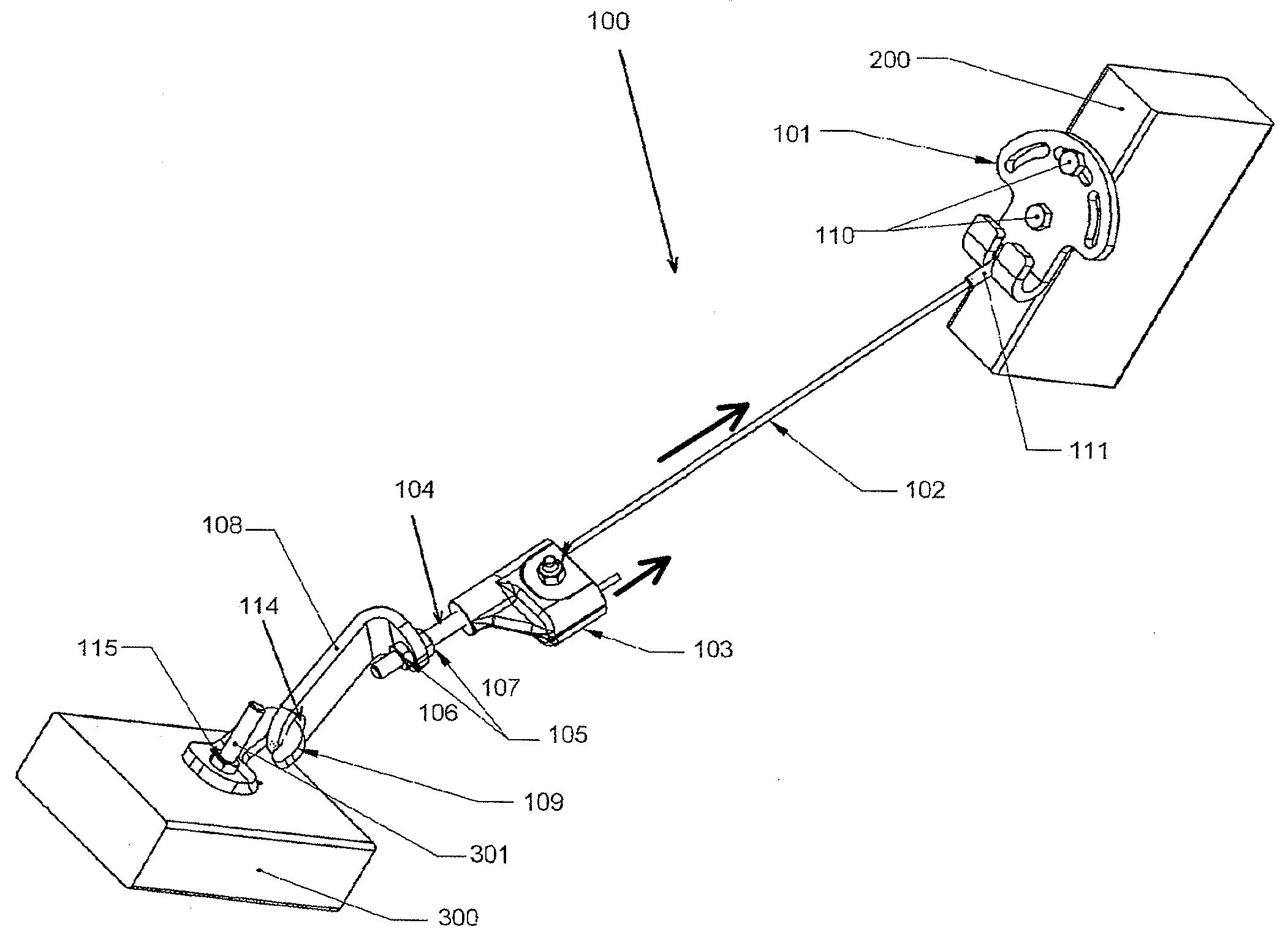
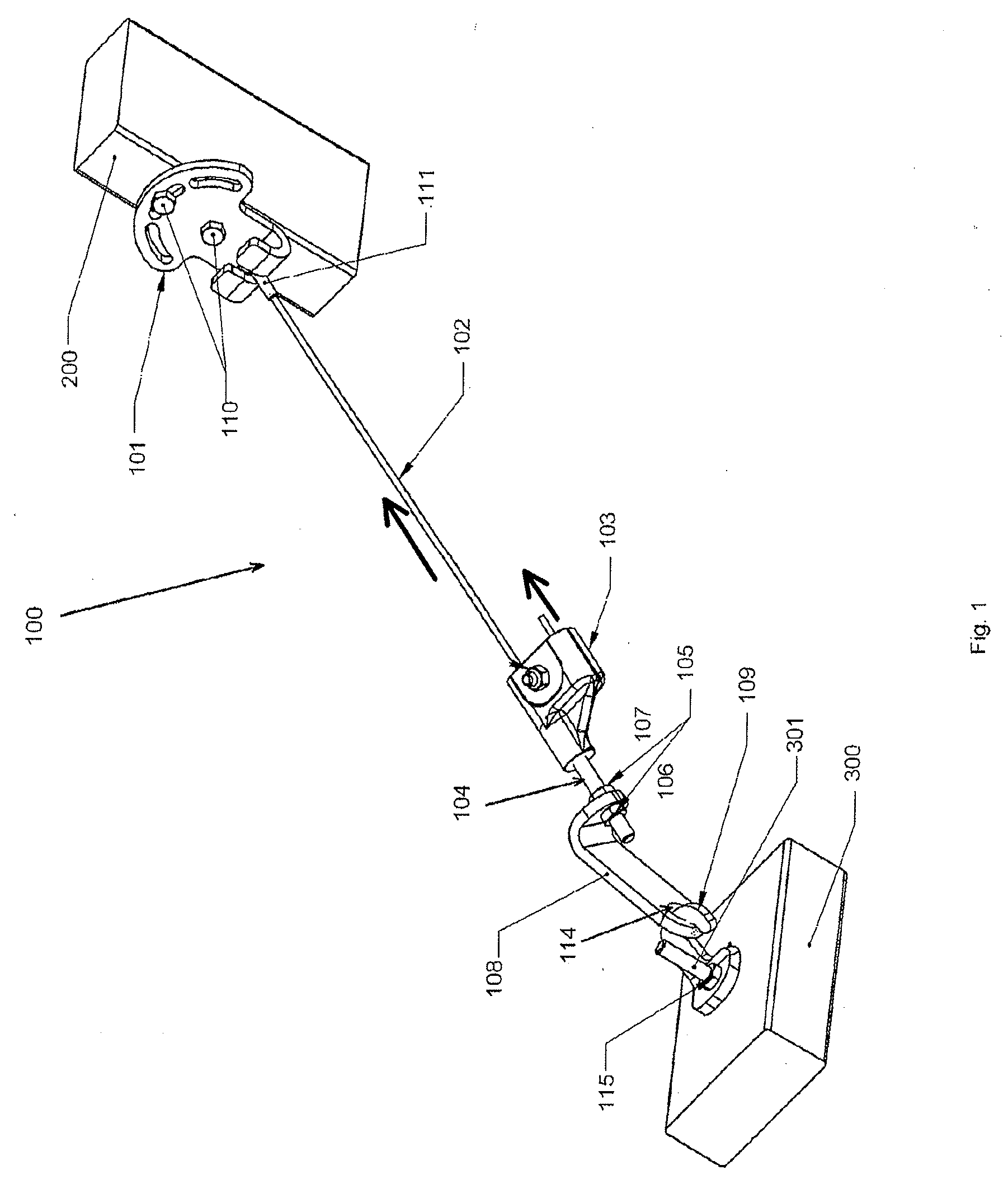
[0027]In accordance with an embodiment of the present invention, a system for adjusting the length and tension of a cable that is used to support another structure, such as bay and bow windows and, more particularly, a system that is easily micro-adjustable as well as macro-adjustable, is provided.

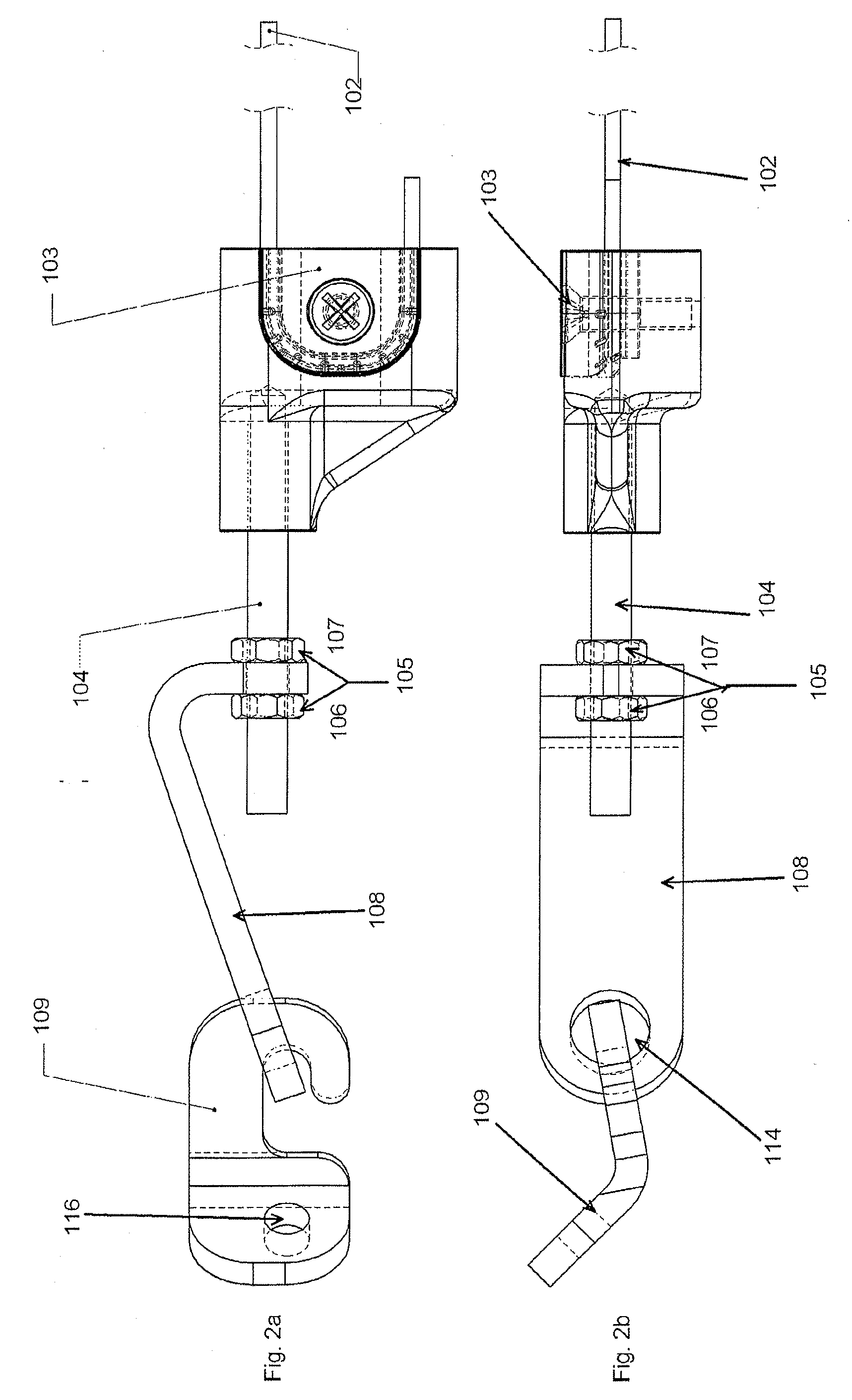
[0028]Turning to FIG. 1, a cable cleat system 100 attached to a wall bracket mounting surface 200 of an exterior wall of a house or other building (not shown) and a window hook mounting surface 300 of a bow or bay window (not shown) according to an embodiment of the present invention, is illustrated. This embodiment shows a cable cleat system 100 comprising a wall bracket 101, a cable 102, a cable clamp assembly 103, a threaded rod 104, a plurality of jam nuts 105, a hook bracket 108, and a window hook or bracket 109. The wall bracket 101 is attached to a wall bracket mounting surface 200, such as an exterior wall or eve of a house, by any fastener means 110 (which may comprise a top faste...


PUM


Abstract

The present invention relates generally to a system for adjusting the length and tension of a cable that is used to support another structure, such as bay and bow windows and, more particularly, to such a system that is easily micro-adjustable as well as macro-adjustable.

Description

RELATED APPLICATIONS[0001]The present application claims priority to U.S. Provisional Application Ser. No. 60 / 890,272, filed Feb. 16, 2007, the entirety of which is hereby incorporated by reference.BACKGROUND OF THE INVENTION 1. Field of Invention[0002]The present invention relates generally to a system for adjusting the length and tension of a cable that is used to support another structure, such as bay and bow windows and, more particularly, to such a system that is easily micro-adjustable as well as macro-adjustable.[0003]2. Description of Prior Art[0004]Bay and Bow windows are types of window units that protrude from the outside wall of a house, typically leaving a “shelf” inside the home that is surrounded by windows on three sides. Since these windows extend out from the house and generally weigh quite a few pounds (and the shelf often holds a variety household objects) it is important that these window units are properly supported. Merely attaching the window units to the fro...

Claims


Application Information

Patent Timeline
IPC IPC(8): E04B1/38
CPCF16G11/12
Inventor TIMOTHY, E. ERIKSIMMONDS, CARL
Owner DEUT BANK AG NEW YORK BRANCH AS COLLATERAL AGENT
Why Eureka
Try Eureka