Parking brake device and vehicle brake system provided with such a parking brake device

a technology of parking brake and brake device, which is applied in the direction of braking system, mechanical apparatus, transportation and packaging, etc., can solve the problems of kink in the force-displacement characteristic curve of the entire arrangement, and achieve the effect of reducing the actuating force, reliable parking brake effect, and less infeed travel

Inactive Publication Date: 2008-08-21
LEITER RALF +2
View PDF3 Cites 2 Cited by
  • Summary
  • Abstract
  • Description
  • Claims
  • Application Information

AI Technical Summary

Benefits of technology

[0006]Against this background, a feature of the present invention is to provide a parking brake device of the initially described type, which with reduced actuating force and less infeed travel guarantees a reliable parking brake effect in particular also after cooling-related shrinkage of brake linings and brake disc.

Problems solved by technology

This leads to a kink in the force-displacement characteristic curve of the entire arrangement.

Method used


Image

  • Parking brake device and vehicle brake system provided with such a parking brake device
  • Parking brake device and vehicle brake system provided with such a parking brake device
  • Parking brake device and vehicle brake system provided with such a parking brake device

Examples


Embodiment Construction

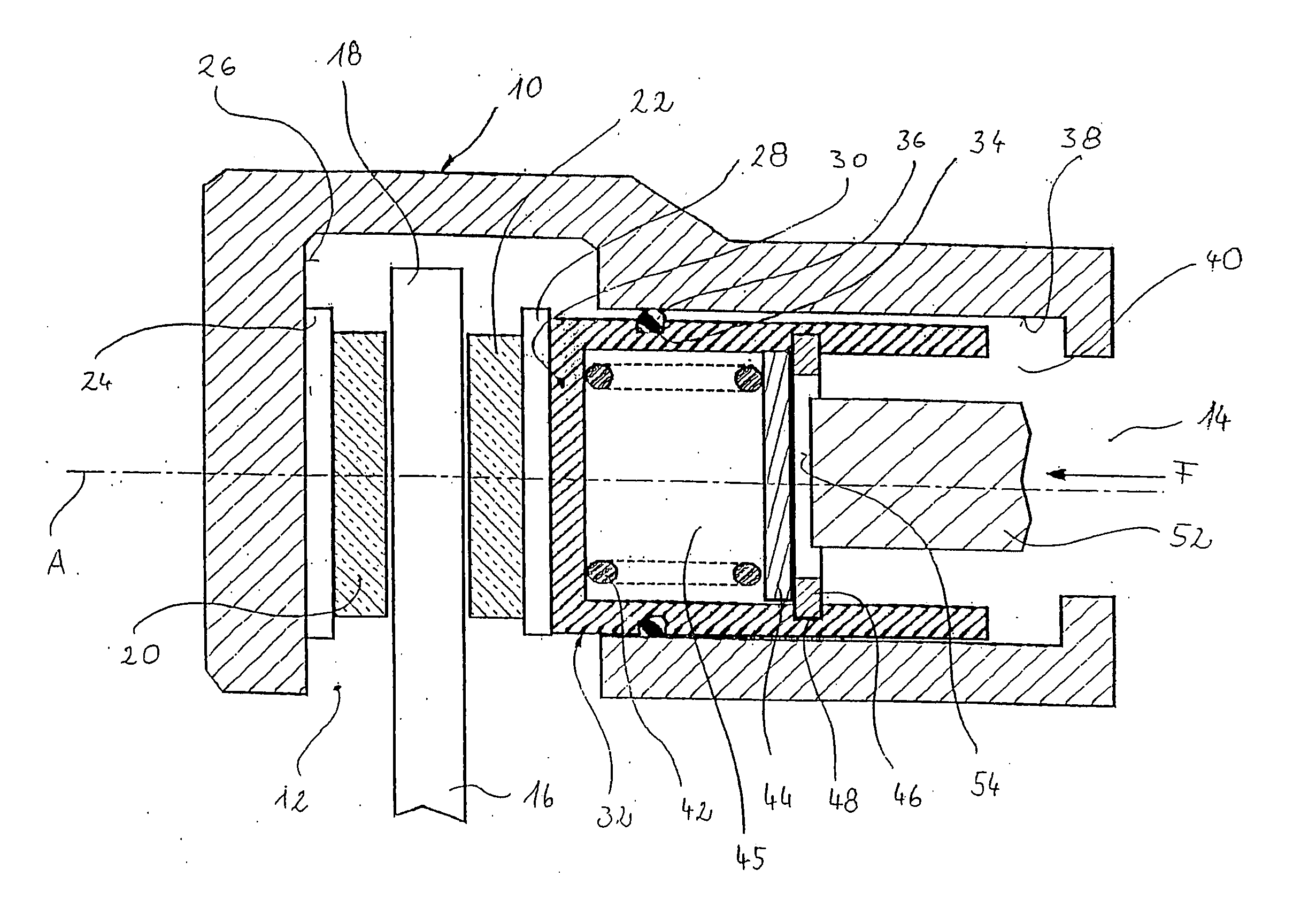
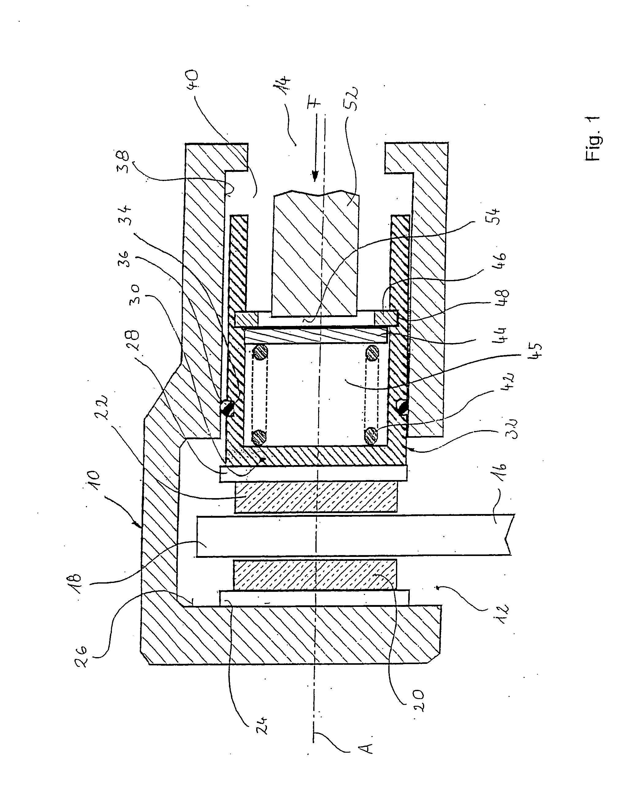
[0023]FIG. 1 shows a part-sectional view of the area close to the brake caliper of a vehicle brake system according to the invention with a parking device in its release position. In particular, FIG. 1 shows a housing 10 with an opening 12 and an opening 14. Projecting into the opening 12 is an only partially illustrated brake disc 16, which is connected to a vehicle wheel that is to be braked and / or immobilized. Brake linings 20 and 22 are disposed on the left and right respectively of a radial end region 18 of the brake disc 16. The brake lining 20 is attached by a stabilizing back plate 24 to the inside 26 of the housing 10. The brake lining 22 is attached by a further stabilizing back plate 28 to the end face 30 of a brake piston 32, which is guided in the housing 10 displaceably along an axis A.

[0024]The housing 10 is float-mounted relative to the brake disc 16. It is therefore possible that, upon an infeed motion of the brake lining 22 towards the brake disc 16 and a frictiona...


PUM


Abstract

The invention relates to a parking brake device comprising a spring element and an actuating element that acts upon the spring element, wherein by applying an actuating force to the actuating element the parking brake device is transferrable between a brake-inactive release position and a brake-active parking position. In the invention, it is provided that the spring element is biased in the release position and that the spring element upon transfer from the release position to the parking position yields only upon attainment of an actuating-force threshold value that is determined by the bias.

Description

CROSS REFERENCE TO RELATED APPLICATIONS[0001]This application is a continuation of U.S. Ser. No. 11 / 184,516, filed Jul. 19, 2005, which is a continuation of International Application No. PCT / EP2004 / 000517 filed Jan. 22, 2004, the disclosures of which are incorporated herein by reference, and which claimed priority to German Patent Application No. 103 02 357.7 filed Jan. 22, 2003, the disclosures of which are incorporated herein by reference.BACKGROUND OF THE INVENTION[0002]The present invention relates to a parking brake device comprising a spring element and an actuating element that acts upon the spring element, wherein by applying an actuating force to the actuating element the parking brake device is transferrable between a brake-inactive release position and a brake-active parking position.[0003]Parking brake devices of this type are prior art. They are provided in a vehicle brake system in order to supply not only a braking effect of the brake system triggered by actuation of ...

Claims


Application Information

Patent Timeline
Patent Type & Authority Applications(United States)
IPC IPC(8): B60T13/04B60T11/04F16D65/14
CPCB60T11/046F16D65/18F16D2125/582F16D2121/14F16D2123/00F16D2121/02
Inventor LEITER, RALFERBEN, RALFPOERTZGEN, GREGOR
Owner LEITER RALF
Why Eureka
Try Eureka