
Method and system for detecting objects using far infrared images

a technology of far infrared and object detection, applied in the field of methods and systems for detecting objects, can solve the problem of still generated high-detectable footprint, and achieve the effect of low cost and low resolution far ir

Inactive Publication Date: 2008-08-21
FORD GLOBAL TECH LLC
View PDF31 Cites 29 Cited by
  • Summary
  • Abstract
  • Description
  • Claims
  • Application Information

AI Technical Summary

Benefits of technology

[0006]In at least one embodiment, a relatively low resolution far IR camera is utilized. The use of a low resolution far IR camera with the methodology of certain embodiments of this invention provides a relatively low cost solution for detecting targets. According to one application, the low resolution far IR camera can be mounted to the front end of a vehicle so that the IR camera, in combination with a detection system, can be utilized to detect pedestrians occupying the space in front of the vehicle and in the far IR camera's field of view.

Problems solved by technology

Conversely, if the pedestrian is cooler than their surroundings, which may occur in desert areas, a highly detectible footprint is still generated.

Method used


Image

  • Method and system for detecting objects using far infrared images
  • Method and system for detecting objects using far infrared images
  • Method and system for detecting objects using far infrared images

Examples


Embodiment Construction

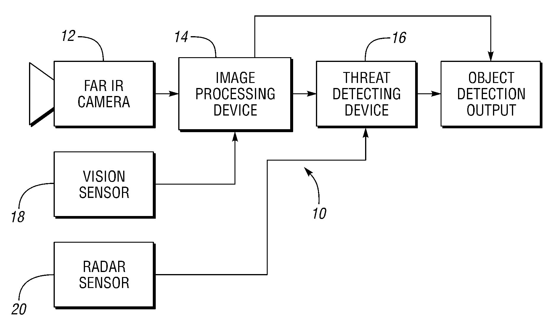
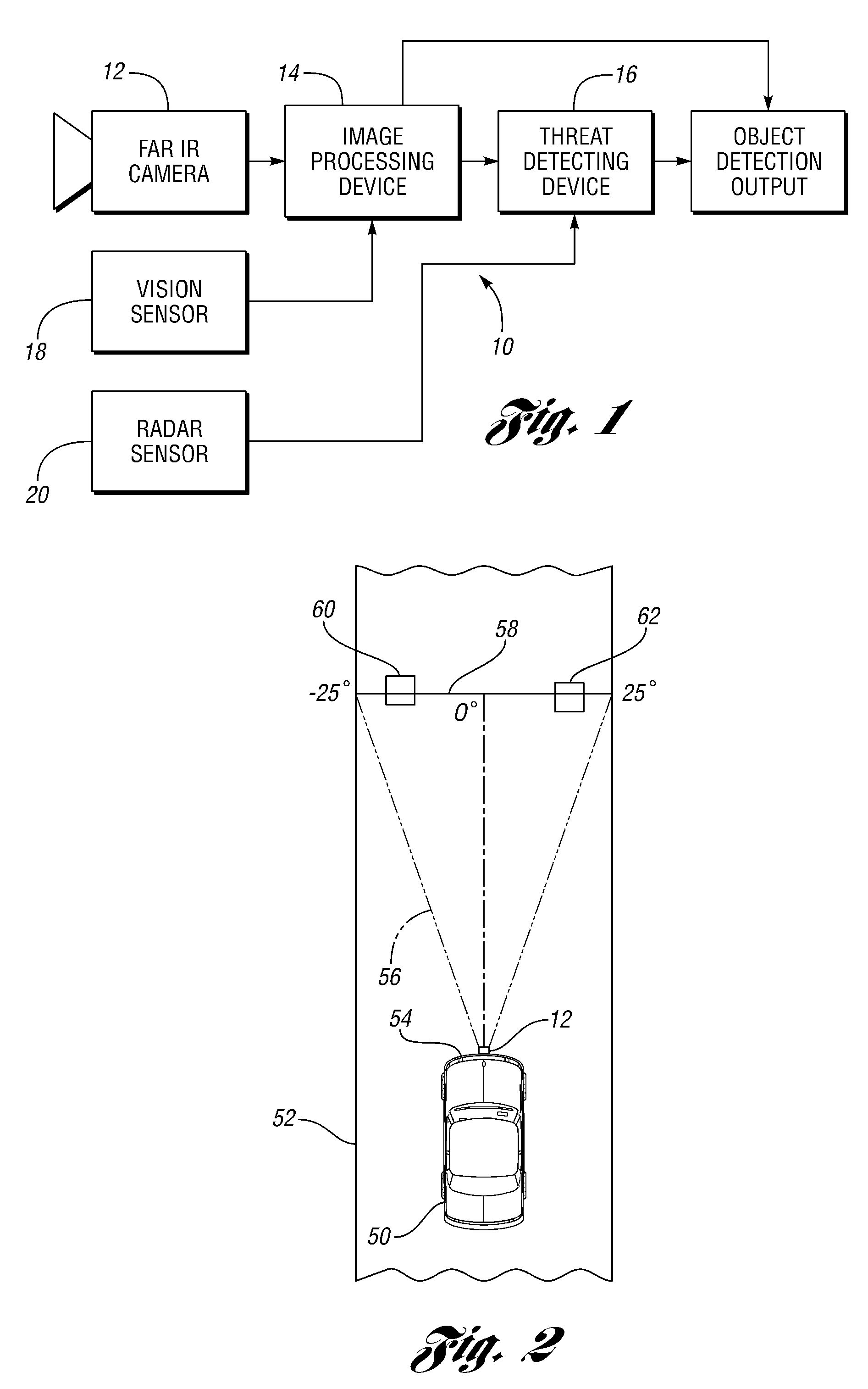
[0027]Turning to the drawings, FIGS. 1 and 2 are described concurrently. FIG. 1 is a block diagram of a detection system 10 and FIG. 2 is a schematic, top view of a vehicle 50 disposed on a road 52, which is depicted as having one lane, however multiple lanes are contemplated by one or more embodiments of the present invention. The detection system 10 includes a far infrared (IR) camera 12, which can be disposed at the front end 54 of vehicle 50 to detect objects, such as targets, and surroundings disposed in front of the far IR camera 12. Targets can be defined as objects that occupy space in front of the vehicle and are detectable by the detection system. Non-limiting examples of targets include pedestrians and animals.

[0028]It should be appreciated that the far IR camera 12 can be disposed at other positions on the vehicle, such as a lateral side of the vehicle or the vehicle rear end, according to different implementations of the present invention.

[0029]The far IR camera 12 sens...


PUM


Abstract

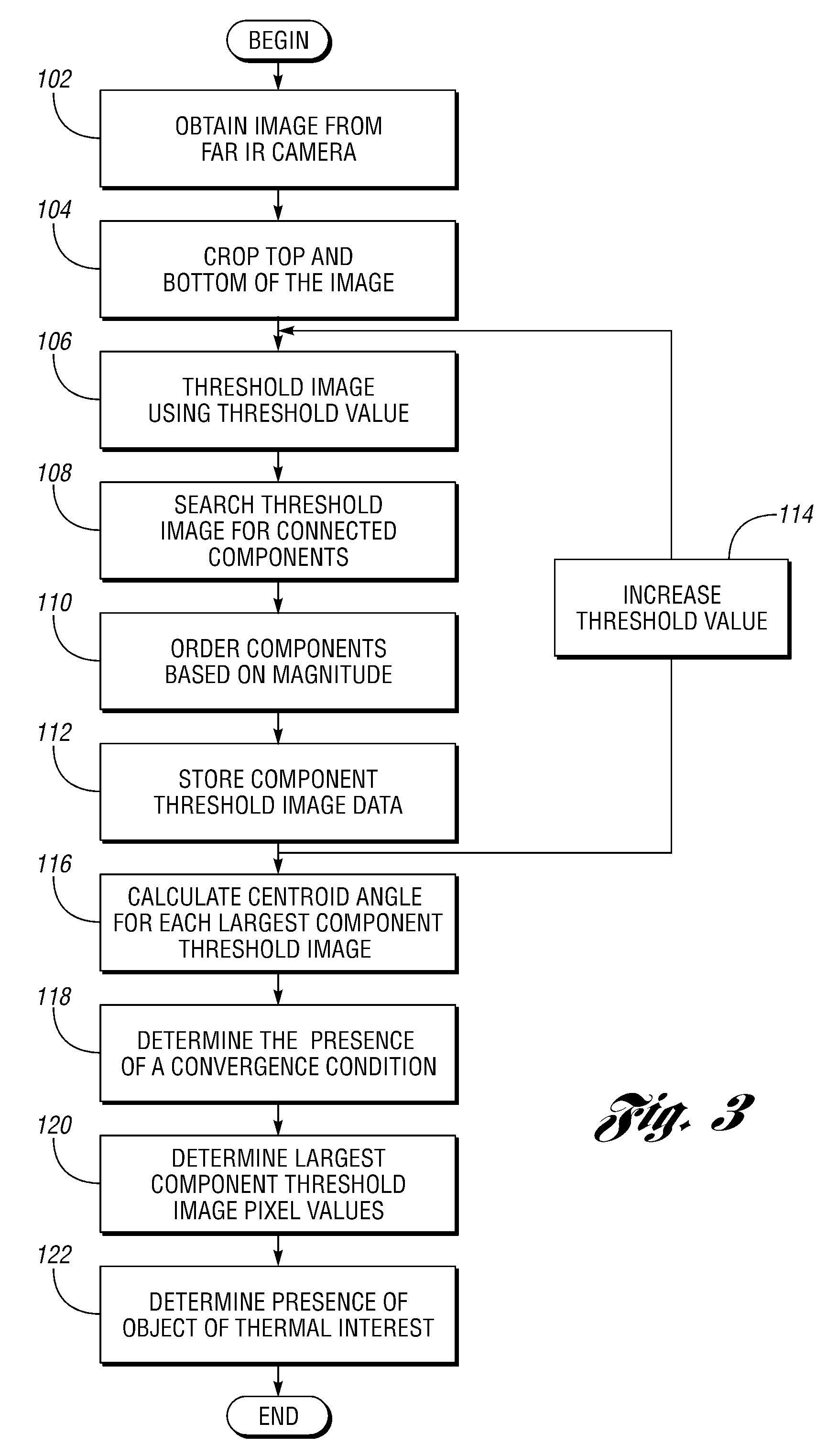
An object detection system is disclosed in at least one embodiment. The system includes a far IR sensor operable to sense thermal radiation of objects and surroundings in a field of view and to generate a far IR image in response thereto, and an image processing device operable to receive and process the far IR image to detect the presence of one or more objects in the field of view. The image processing device can be configured to process the far IR image by generating an initial threshold image based on the far IR image and an initial threshold value, iteratively obtaining a number of successive threshold images based on the far IR image and a number of successively increased threshold values, and determining the presence of one or more objects in the field of view based on the threshold images and threshold values.

Description

BACKGROUND[0001]1. Technical Field[0002]One aspect of the present invention generally relates to a method and system for detecting objects, such as pedestrians and animals, using far infrared images.[0003]2. Background Art[0004]Many pedestrian detection systems have been proposed to mitigate pedestrian injuries resulting from the operation of vehicles. The typical pedestrian detection system includes one or more sensors mounted to the front of the vehicle for sensing conditions relating to the space in front of the vehicle to obtain data, which is transmitted to an onboard image processing unit. The image processing unit processes the collected data to detect whether a pedestrian occupies the space in front of the vehicle. If a pedestrian is detected, then the processing unit sends a signal to a vehicle warning system to alert the driver so that measures can be taken to avoid contact between the vehicle and the pedestrian. Moreover, the signal can be transmitted to an autonomous bra...

Claims


Application Information

Patent Timeline
IPC IPC(8): H01L31/00
CPCB60R1/00B60R21/34B60R2300/106B60R2300/301B60R2300/8053G06K9/00805G06T7/0081G06T2207/10048G06T2207/20148G06T2207/30261H04N5/33B60T7/22G06T7/11G06T7/136G06V20/58H04N23/23
Inventor EBENSTEIN, SAMUELSMITH, GREGORYPRAKAH-ASANTE, KWAKURODIN, YELENAZORKA, NICHOLAS
Owner FORD GLOBAL TECH LLC
Learn More