Surface-mount type crystal unit

a surface-mounting, crystal unit technology, applied in piezoelectric/electrostrictive/magnetostrictive devices, piezoelectric/electrostriction/magnetostriction machines, electrical equipment, etc., can solve the problem of not being able to precisely detect the actual operating temperature of the crystal unit, not being able to compensate further, and the frequency-temperature characteristic of the crystal unit cannot be sufficiently compensated. problem, to achieve the effect of small swing width of th

Active Publication Date: 2008-08-21
NIHON DEMPA KOGYO CO LTD
View PDF3 Cites 14 Cited by
  • Summary
  • Abstract
  • Description
  • Claims
  • Application Information

AI Technical Summary

Benefits of technology

[0017]Generally, a thermistor is a tall electronic part in comparison with a necessary interval from a surface of a crystal blank to an inner bottom surface of a concavity, and to a cover. When such a thermistor is arranged as it is in the inner bottom surface of the concavity, it is necessary to enlarge a space between the inner bottom surface of the concavity and the cover, and hence, swing width of the other end part of the crystal blank becomes large when mechanical vibration is applied to the crystal blank. When the swing width of the other end part becomes large, a large stress is applied to a holding system of the electrical conductive adhesive and the like which fixes the crystal blank to the crystal holding terminals, and hence, there is a possibility of causing a change of an oscillating frequency, and the like. Then, in the present invention, it is preferable not only to stack two or more layers to construct the bottom wall layer, but also to make the other end part of the crystal blank face a top layer of the bottom wall layer, and to make the top layer removed at least in the hollow part. According to such construction, it is possible not only to reduce the interval between the inner bottom surface of the concavity, and the cover in a position of the other end part of the crystal blank, but also to arrange the other end part of the crystal blank in a midrange between the inner bottom surface and cover, and to make the swing width of the other end part of the crystal blank small and equal vertically.

Problems solved by technology

Hence, since detection temperature by the temperature sensor in IC chip 11 becomes different from actual operating temperature of crystal blank 4, a problem that the frequency-temperature characteristic of the crystal unit cannot be sufficiently compensated arises.
In this crystal oscillation module, although an influence of heat generation of the IC chip is reduced since the thermistor for temperature detection is separately arranged from the IC chip, the thermistor is arranged in the external of the crystal unit, and hence, strictly speaking, it is not possible to detect the actual operating temperature of the crystal unit exactly, and it is not possible to compensate further adequately the frequency-temperature characteristic accordingly.

Method used


Image

  • Surface-mount type crystal unit
  • Surface-mount type crystal unit
  • Surface-mount type crystal unit

Examples


first embodiment

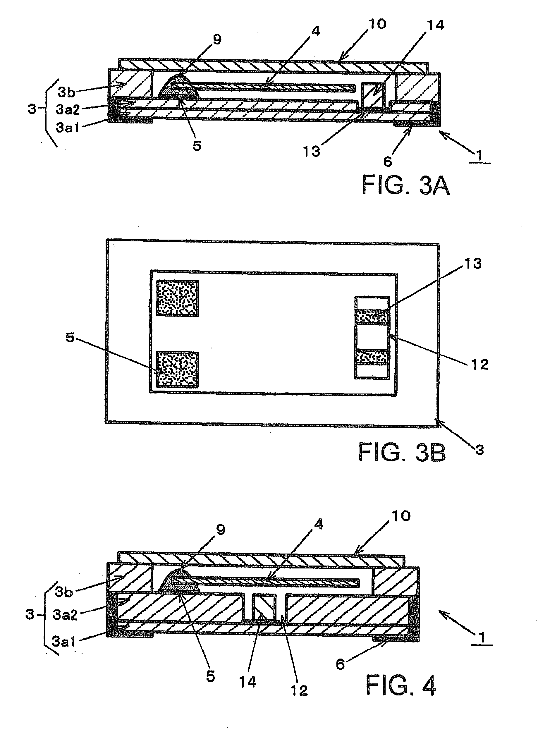
[0023]In FIGS. 3A and 3B illustrating the crystal unit of the first embodiment of the present invention, the same reference symbols are assigned to the same components as those in FIGS. 1 and 2, and duplicated descriptions about these will be simplified or omitted.

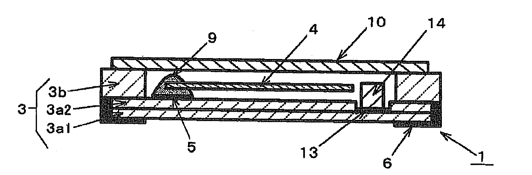
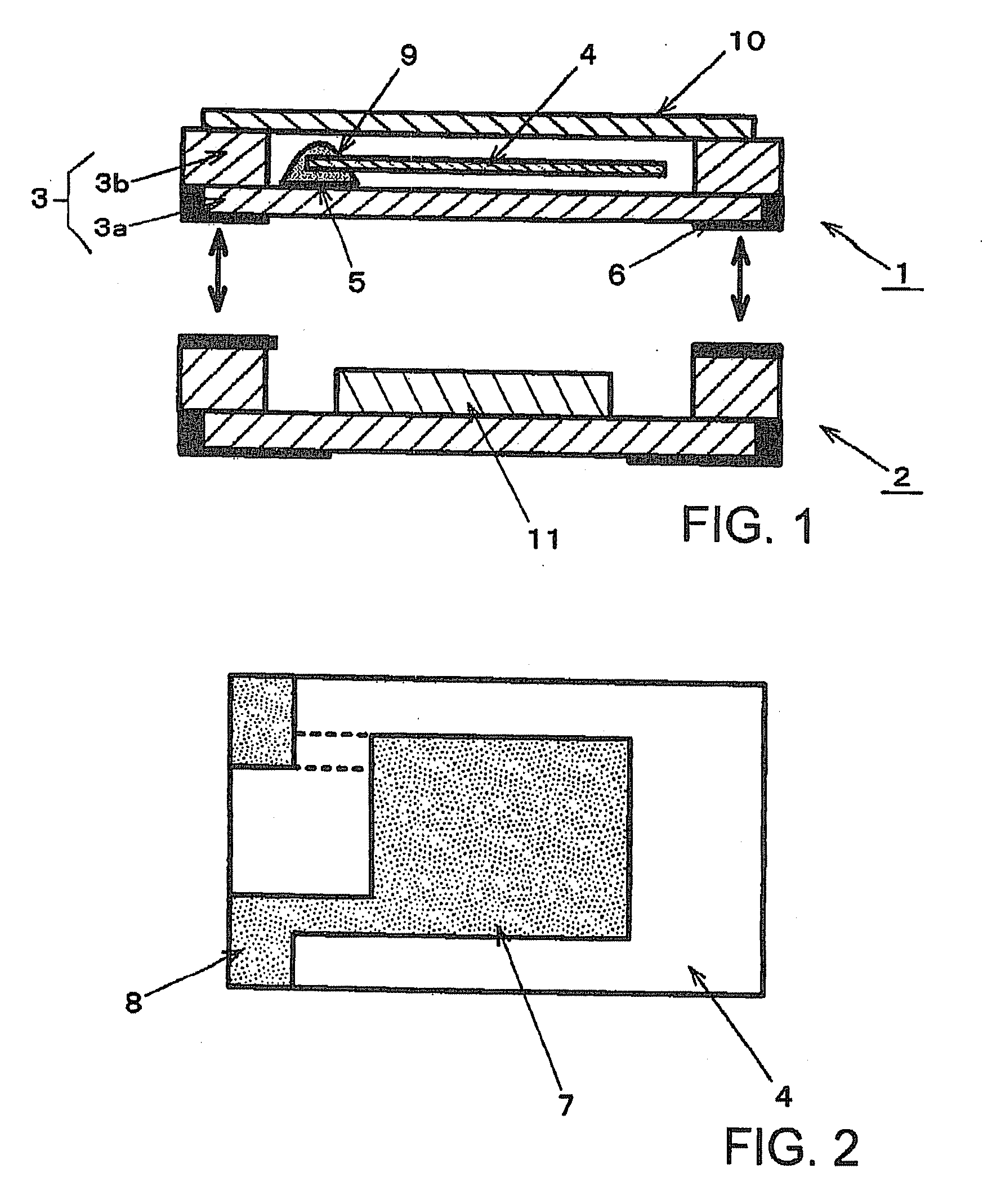
[0024]The surface-mount type crystal unit illustrated in FIGS. 3A and 3B is suitably used for incorporating in a temperature compensated crystal oscillator and hermetically seals crystal blank 4 in a concavity by accommodating crystal blank 4 in the concavity of package body 3 and covering metal cover 10 to the concavity. As mentioned above, package body 3 is constructed of a laminated ceramic, and has bottom wall layer 3a and frame wall layer 3b which has an opening and is formed on bottom wall layer 3a, and in which the concavity is constructed of the opening.

[0025]External terminals 6 are formed on an outer bottom surface of package body 3, that is, square corners of a bottom surface of bottom wall layer 3a, respectivel...

second embodiment

[0032]In FIG. 4 illustrating a crystal unit of the second embodiment of the present invention, the same reference symbols are assigned to the same components as those in FIGS. 3A and 3B, and duplicated descriptions about these will be omitted or simplified.

[0033]In crystal unit 1 of the second embodiment, hollow part 12 is provided in a central area of the inner bottom surface in package body 2, and thermistor 14 is arranged in this hollow part 12. Hence, excitation electrode 7 of crystal blank 4 is opposite above hollow part 12. At this time, a top face of thermistor 14 and a top face of top layer 3a2 of bottom wall layer 3a are in an identical level.

[0034]According to this construction, since thermistor 14 is arranged in a position nearest to an excitation portion of crystal blank 4, that is, a vibration displacement region, it becomes possible to detect actual operating temperature of crystal blank 4 further exactly. Then, similarly to the first embodiment, since the other end pa...


PUM


Abstract

A surface-mount type crystal unit includes a package body which is made of a laminated ceramic and has a bottom wall layer and a frame wall formed on the bottom wall layer, the frame wall layer having an opening. In the package body, a concavity is constructed of the opening. The crystal unit further includes a pair of crystal holding terminals formed on one end part of the inner bottom surface of a concavity which is a top face of the bottom wall layer; a crystal blank held in the concavity by fixing the both sides of the one end part of the crystal blank to the pair of crystal holding terminals; a thermistor; and a cover which closes the concavity. The thermistor is arranged in a hollow part arranged in the top face of the bottom wall layer in the concavity.

Description

BACKGROUND OF THE INVENTION[0001]1. Field of the Invention[0002]The present invention relates to a surface-mount type crystal unit, and in particular, to a surface-mount type crystal unit preferably used for a temperature compensated crystal oscillator and the like.[0003]2. Description of the Related Art[0004]Since a surface-mount type quartz crystal unit in which a quartz crystal blank is hermetically sealed in a surface-mounting package is small and lightweight, for example, it is incorporated in a crystal oscillator as a reference source of a frequency or time in portable electronic equipment. By detecting operating temperature of a crystal unit and compensating a frequency change on the basis of a frequency-temperature characteristic of the crystal unit, a temperature compensated crystal oscillator among such crystal oscillators supplies an oscillation signal at a fixed frequency regardless of a change of the ambient temperature. FIG. 1 illustrates construction of an example of ...

Claims


Application Information

Patent Timeline
Patent Type & Authority Applications(United States)
IPC IPC(8): H01L41/053
CPCH03H9/0542H03H9/1021H03H9/0547
Inventor MIYAHARA, ITARUAKANE, KATSUNORI
Owner NIHON DEMPA KOGYO CO LTD
Why Eureka
Try Eureka