LED driver touch switch circuit

a technology for driving and touch switches, applied in the field of vehicle illumination, can solve the problems of large change of current, incandescent light bulbs are typically not energy efficient, and have a much shorter life than other lighting systems, so as to reduce the number of electrical circuits and reduce the number of analog comparator circuits

Inactive Publication Date: 2008-08-21
LEAR CORP
View PDF13 Cites 42 Cited by
  • Summary
  • Abstract
  • Description
  • Claims
  • Application Information

AI Technical Summary

Benefits of technology

[0011]The present invention has the advantage of reducing a number of electrical circuits required for illuminating a LED illumination source by utilizing a single integrated circuit to receive sensed inputs and pulse width drive an LED driver

Problems solved by technology

However, standard incandescent light bulbs are typically not energy efficient and have a much shorter life than other lighting systems.
Incandescent light bulbs have high thermal losses, and as a result, temperature concerns must be taken into consideration when packaging the incandescent lights in specific regions of the vehicle.
As a result of the heat dissipation, the effect of the heat on various surrounding components result in the use of costly materials having superior thermal properties for shielding the dissipated heat from various surrounding components which may otherwise cause adverse affects.
Small voltage changes in the supply to a LED may result in a large change in current.
In addition, mos

Method used


Image

  • LED driver touch switch circuit
  • LED driver touch switch circuit
  • LED driver touch switch circuit

Examples


Embodiment Construction

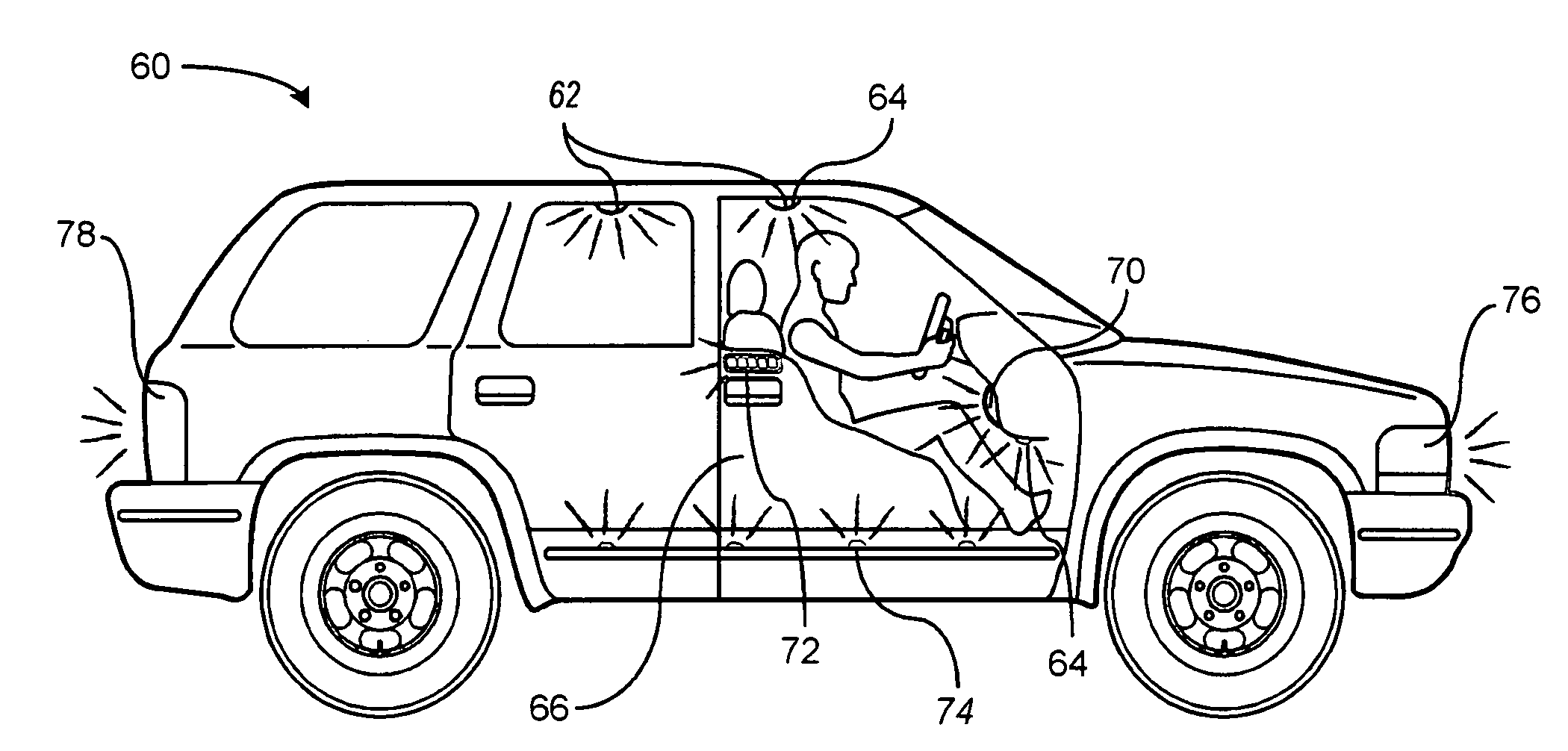
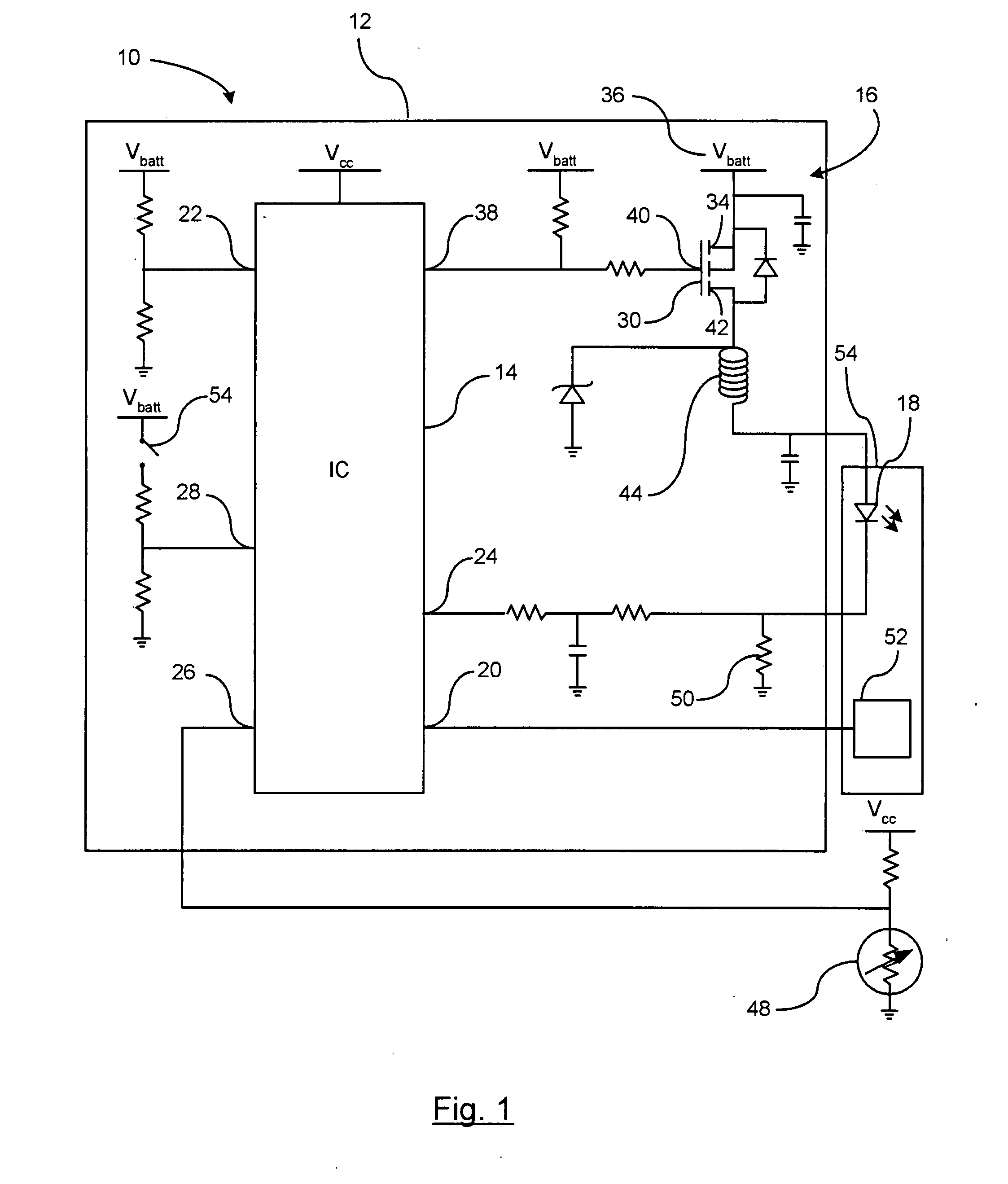
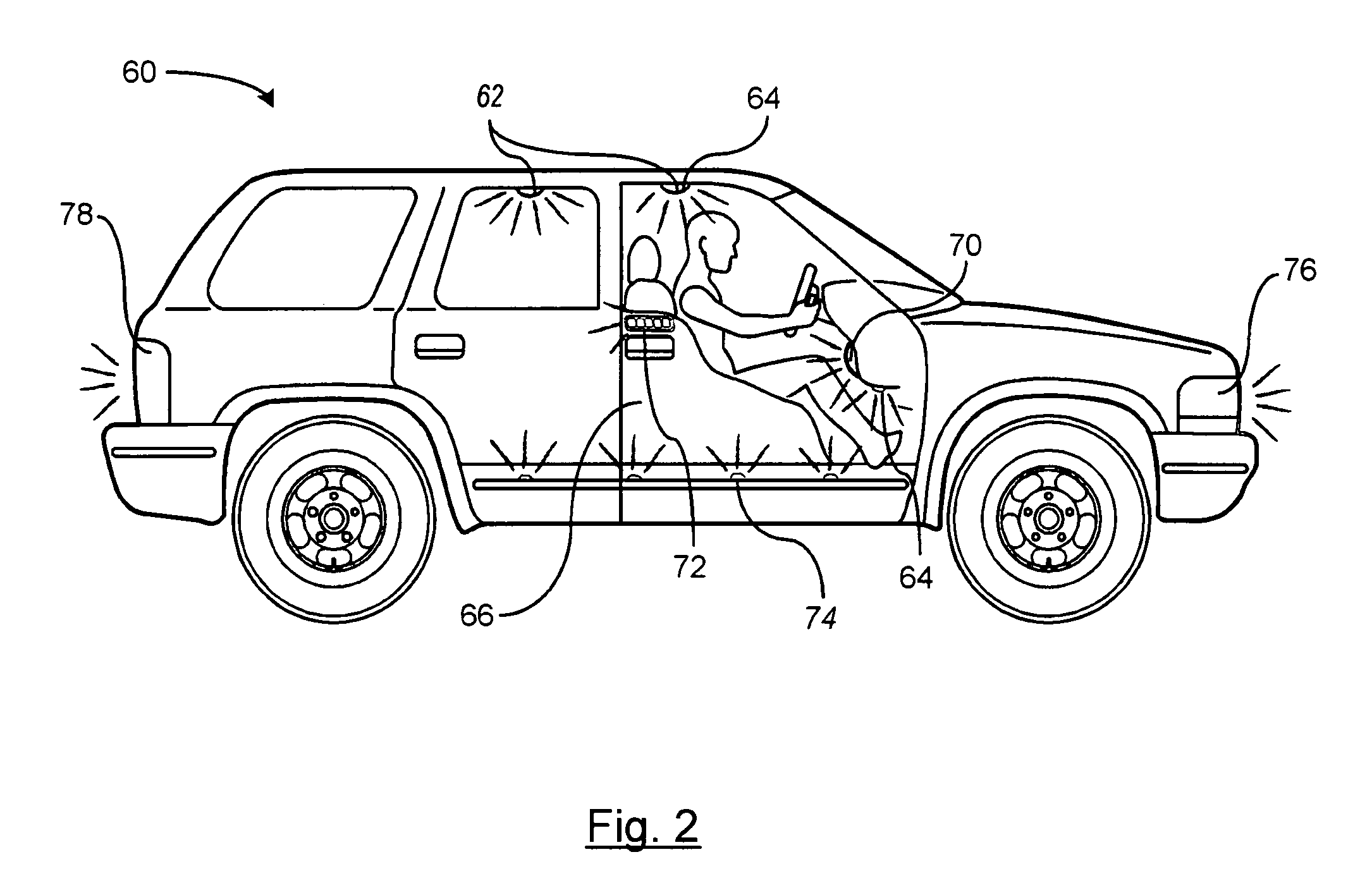
[0018]There is shown in FIG. 1 a touch switch LED illumination circuit 10 for a vehicle. The touch switch LED illumination circuit 10 includes a printed circuit board (PCB) 12. The PCB 12 includes an integrated circuit 14 and a drive circuit shown generally at 16.

[0019]The integrated circuit 14 operates to control the illumination intensity of the illumination source 18 such as a LED which is mounted remote from the PCB 12. The integrated circuit 14 receives various inputs and provides a control voltage to the drive circuit 16 for variably controlling the current provided to the illumination source 18. The integrated circuit 14 receives inputs such as an illumination on / off command input 20, a sensed battery voltage input 22, an illumination source current draw input 24, and temperature sense input 26. The integrated circuit 14 may also include a door switch input 28.

[0020]The driver circuit 16 preferably includes a FET 30, or similar device, electrically coupled to the illumination...


PUM


Abstract

A vehicular touch switch activated LED illumination circuit includes a LED illumination source for providing vehicle illumination. A touch switch antenna senses a user input for activating and deactivating the LED illumination source. An integrated circuit mounted to a printed circuit board for controlling the current provided to the LED illumination source. The integrated circuit is in communication with the touch switch antenna for detecting the user input. A driver circuit is mounted to the printed circuit board and is electrically coupled to the LED illumination source for driving the LED illumination source. The integrated circuit includes a battery voltage sensed input and a temperature sensed input for receiving sensed input signals to control a signal input to the driver circuit for variably controlling the current provided to the illumination source.

Description

CROSS-REFERENCE TO RELATED APPLICATIONS[0001]Not ApplicableSTATEMENT REGARDING FEDERALLY SPONSORED RESEARCH OR DEVELOPMENT[0002]Not ApplicableREFERENCE TO A SEQUENCE LISTING, A TABLE, OR A COMPUTER PROGRAM LISTING COMPACT DISC APPENDIX[0003]Not ApplicableBACKGROUND OF THE INVENTION[0004]1. Field of Invention[0005]This invention relates in general to vehicle illumination, and more specifically, to LED vehicle illumination.[0006]2. Background of Related Art[0007]Incandescent lighting systems have been extensively used for vehicle interior and exterior lighting systems. Incandescent lamps provide a simple and inexpensive electrical lighting system by only requiring a voltage supply to energize a resistive element within the incandescent light, known as a filament, for vehicle illumination. Current is applied to the filament within a glass casing of the bulb causing it to heat up and emit light. However, standard incandescent light bulbs are typically not energy efficient and have a muc...

Claims


Application Information

Patent Timeline
IPC IPC(8): B60Q1/24F21W107/10
CPCB60Q1/323B60Q3/0279B60Q3/0296B60Q3/0293B60Q3/0286B60Q3/82B60Q3/74B60Q3/76B60Q3/80B60Q2500/30B60Q1/324
Inventor CRUICKSHANK, WILLIAM
Owner LEAR CORP
Why Eureka
Try Eureka