Sheet cutting device and printer

a cutting device and printer technology, applied in printing, manufacturing tools, metal working devices, etc., can solve the problems of affecting the movable blade, the print head or the platen roller being moved, and the movable blade being disabled in some cases, so as to achieve easy and reliable elimination of sheet material

Active Publication Date: 2008-08-21
SEIKO INSTR INC
View PDF6 Cites 16 Cited by
  • Summary
  • Abstract
  • Description
  • Claims
  • Application Information

AI Technical Summary

Benefits of technology

[0023]As described above, according to the present invention, the stationary blade frame or the movable blade frame is provided so as to be movable with respect to the main frame while the position of the printin...

Problems solved by technology

In the related art sheet cutting device, when the sheet material is being cut, due to paper jam, the movable blade is disabled in some cases.
As disclosed in Patent Document 1, in the structure in which the stationary blade moves together with the print head or the platen roller, there is a risk of the print head or the platen roller being moved before a release operation in which the movable blade is moved with respect to the stationary blade to the cutting stand-by position.
Further, there is a risk of the print head or the platen roller impacting on the movable blade which has not been completely moved to the cutting stand-by position.
Thus, there is a problem in that ...

Method used


Image

  • Sheet cutting device and printer
  • Sheet cutting device and printer
  • Sheet cutting device and printer

Examples


Embodiment Construction

[0034]Hereinafter, a specific embodiment of the present invention will be described with reference to the drawings.

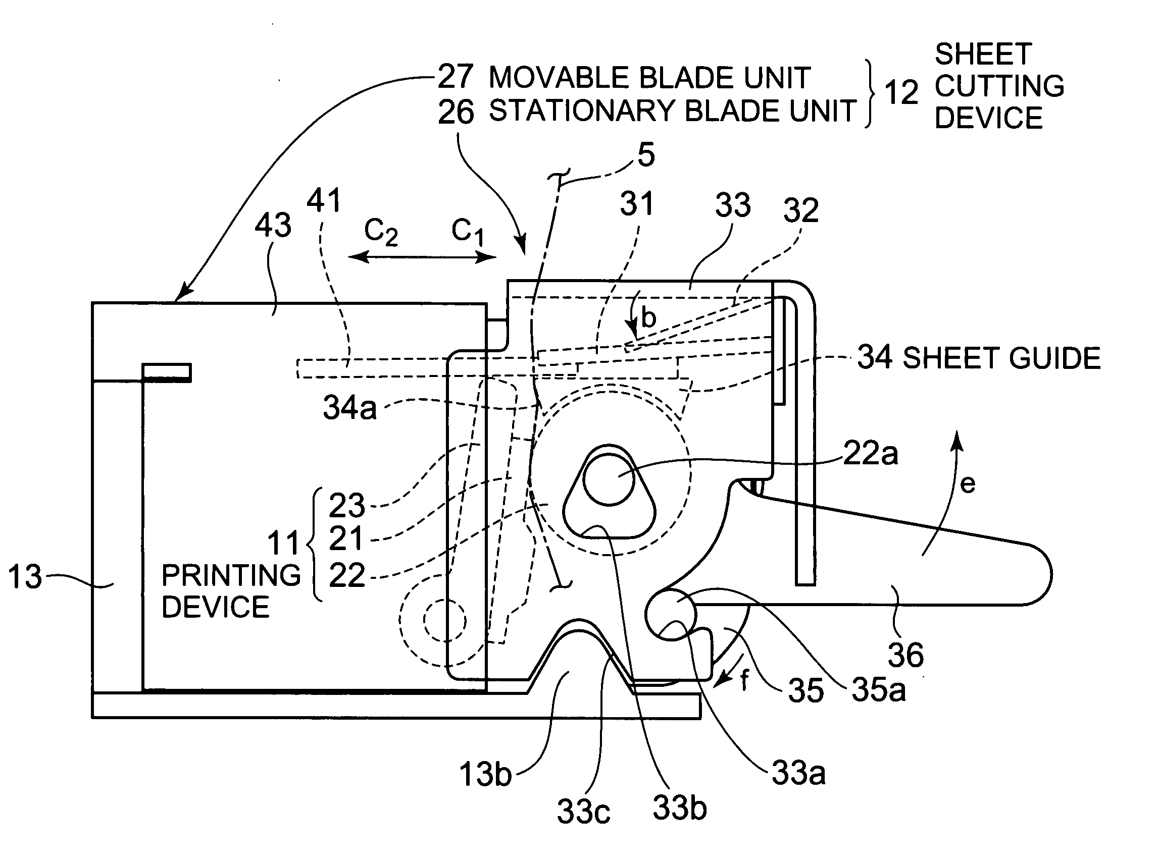
[0035]A printer according to this embodiment is a printer in which printing is performed on the sheet material, and the sheet material is then cut to have a predetermined length, and in which a stationary blade frame is attached to a detachable platen roller of a printing device. For the sheet material used in the printer of this embodiment, there is employed so-called heat sensitive paper having a heat-sensitive printing layer provided on a surface side of a sheet-like base material.

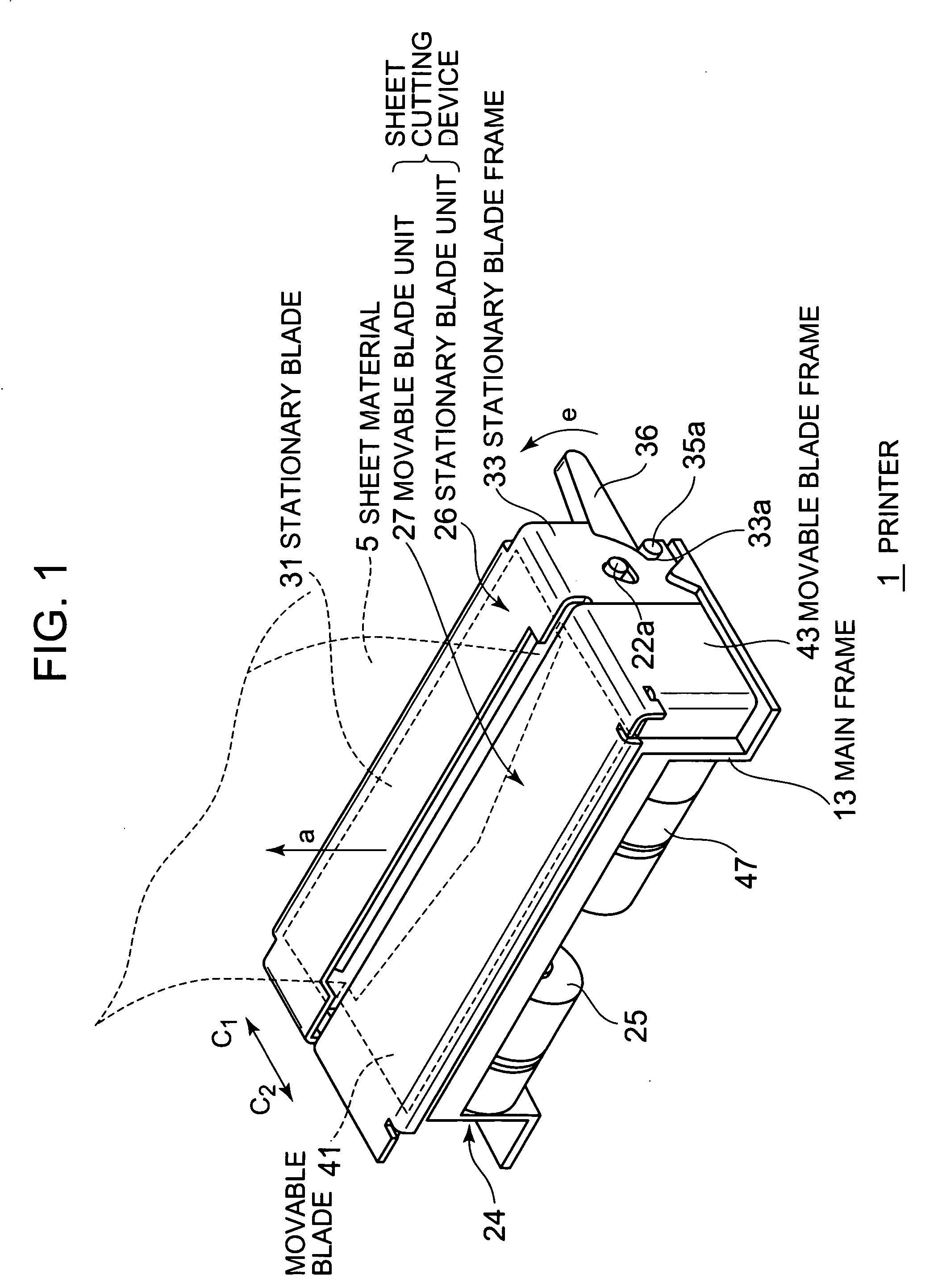
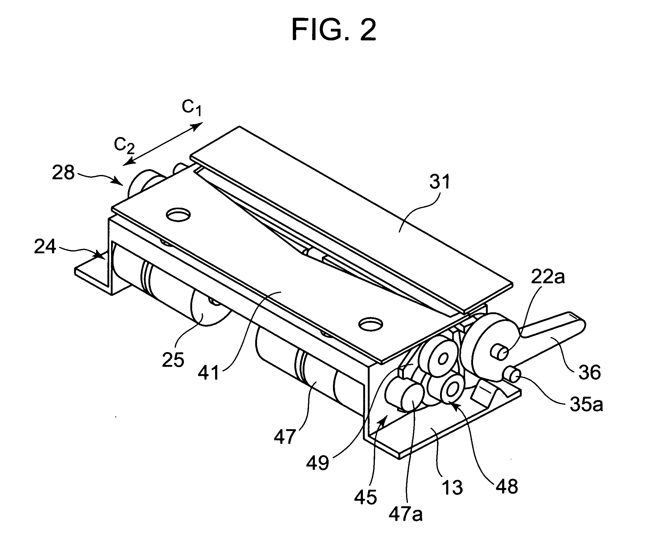
[0036]FIG. 1 is a perspective view showing a printer of this embodiment. FIG. 2 is a perspective view of a sheet cutting device with a movable blade frame and the stationary blade frame being omitted. FIG. 3 is a perspective view showing a state in which a stationary blade unit is removed from a main frame of the sheet cutting device. FIG. 4 is a see-through side view showing a state where ...


PUM


Abstract

A stationary blade (31) is disposed on a downstream side in a transporting direction of a sheet material (5) with respect to a movable blade (41). A sheet cutting device (12) includes a stationary blade frame 33 supporting the stationary blade (31), a movable blade frame (43) supporting the movable blade (41), and a main frame (13) which movably supports the stationary blade frame (33) and to which the movable blade frame (43) is fixed. The stationary blade frame (33) is movably provided with the main frame (13) such that the stationary blade (31) is moved to a release position where a press contact state between the stationary blade (31) and the movable blade (41) is released while retaining a position of a printing device (1).

Description

BACKGROUND OF THE INVENTION[0001]1. Field of the Invention[0002]The present invention relates to a sheet cutting device for cutting a sheet material by a stationary blade and a movable blade after performing printing on the sheet material such as roll paper, and to a printer including the sheet cutting device.[0003]2. Description of the Related Art[0004]Conventionally, as a printer which performs printing on a sheet material in a form of roll paper, there exist a printing device for performing printing on the sheet material sandwiched between a print head and a platen roller, and a printer including a sheet cutting device for cutting the sheet material on which the printing has been performed by the printing device. As the sheet cutting device included in the printer of this type, there is known a sheet cutting device in which a movable blade moves with respect to a stationary blade, thereby cutting a sheet material.[0005]In the related art sheet cutting device, when the sheet mater...

Claims


Application Information

Patent Timeline
IPC IPC(8): B41J11/70B26D1/02B26D5/08B26D1/06
CPCB26D1/085B41J11/70B26D7/2614B26D5/02Y10T83/8822Y10T83/687B41J11/66B41J11/00
Inventor KOHIRA, HIROYUKI
Owner SEIKO INSTR INC
Why Eureka
Try Eureka