Mounting assembly

a technology of mounting assembly and tolerance ring, which is applied in the direction of magnetic recording, physics instruments, rod connections, etc., can solve the problems of assembly force size and compression force, and achieve the effect of less sensitive to compression force variations, less assembly force for tolerance ring, and greater control of resonant frequency

Active Publication Date: 2008-08-21
SAINT GOBAIN PERFORMANCE PLASTICS RENCOL
View PDF18 Cites 67 Cited by
  • Summary
  • Abstract
  • Description
  • Claims
  • Application Information

AI Technical Summary

Benefits of technology

[0011]At its most general, the invention provides a tolerance ring for delicate assemblies having a configuration which makes it less sensitive to variations in compression force. Thus, various properties exhibited by the tolerance ring may be more stable over a given variation in size between an inner and an outer component. Fo

Problems solved by technology

These components are delicate, which imposes constraints on the

Method used


Image

  • Mounting assembly
  • Mounting assembly
  • Mounting assembly

Examples


Embodiment Construction

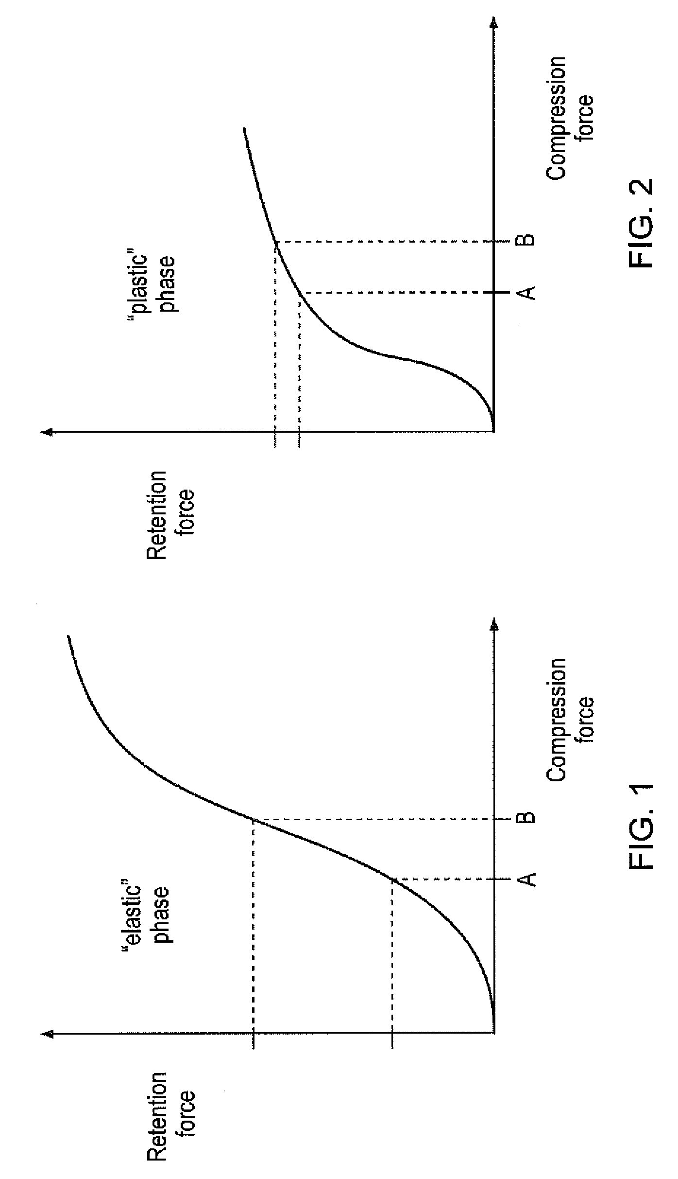
[0036]FIGS. 1 and 2 are schematic representations of compression force / retention force profiles that are useful for illustrating the invention. The profile shown in FIG. 1 is illustrative of a profile of a conventional tolerance ring used for a delicate apparatus, such as a hard disk drive pivot mount. To prevent damage to the components of the apparatus, the force by which the tolerance ring is compressed between the components is limited to the range A-B shown in FIG. 1. In conventional tolerance rings, this range corresponds to an “elastic” phase of the characteristic behaviour of a tolerance ring. The compression force range A-B therefore corresponds to a wide range of retention forces. Since the actual value of the compression force depends on the relative sizes of the components of the apparatus, small variations in size can lead to large variation in the size of the retention force. The actual value for the retention force is therefore unstable. A disadvantage of this is that...


PUM


Abstract

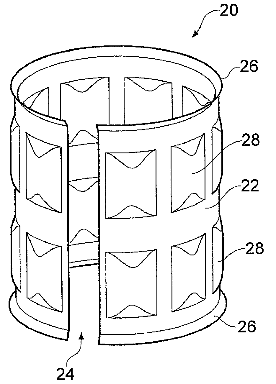
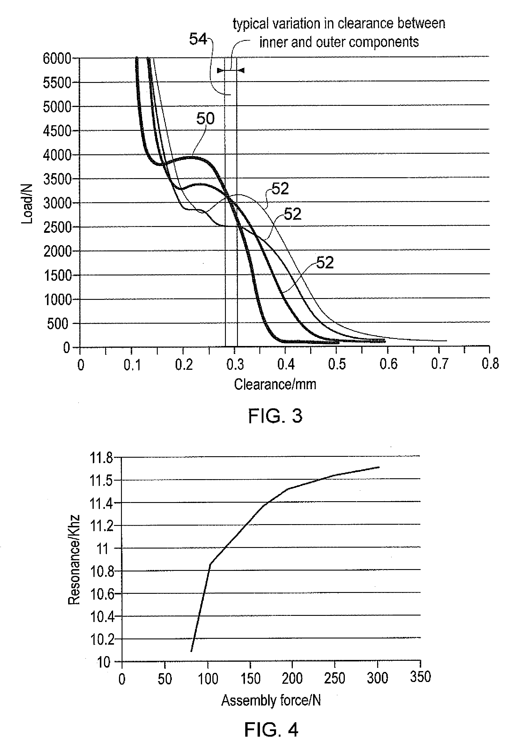
A mounting assembly comprising mating inner and outer components (36, 38) mounted together using a tolerance (20) is disclosed. The tolerance ring (20) has radially extending projections (28) that are configured to cause the tolerance ring (20) to operate into the plastic phase of its compression force/retention force characteristic. This can be achieved by using softer projections than those found in conventional tolerance rings. The force required to mount the tolerance ring and a range of retention forces exhibited by it for a given variance in sizes of mating components is thereby stabilised.

Description

CROSS REFERENCE TO RELATED APPLICATION[0001]This application is a utility patent application based on U.S. Provisional Patent Application No. 60 / 890,736 filed on Feb. 20, 2007, the benefit of which is hereby claimed under 35 U.S.C. § 119 and the disclosure of which is herein incorporated by reference in its entirety.FIELD OF THE INVENTION[0002]The invention relates to apparatus comprising mating inner and outer components, which are mounted together using a tolerance ring. For example, the invention can be used for mounting a shaft in a bore formed in a housing.BACKGROUND OF THE INVENTION[0003]It is known to connect together mating inner and outer components using a tolerance ring. For example, a tolerance ring may be used to hold a shaft in place in a corresponding bore, or it may act as a force limiter to permit torque to be transmitted between the shaft and the housing. The use of a tolerance ring accommodates minor variations in the diameter of the inner and outer components wit...

Claims


Application Information

Patent Timeline
IPC IPC(8): F16B7/02
CPCF16C11/04F16C27/00F16C35/077F16D1/0835Y10T403/7061G11B5/4813G11B25/043G11B33/12F16C2370/12F16D2001/062
Inventor BAKER, MARCUSSLAYNE, ANDREW
Owner SAINT GOBAIN PERFORMANCE PLASTICS RENCOL
Why Eureka
Try Eureka