

Respiration suppressing mat and magnetic resonance imaging apparatus and method
- Summary
- Abstract
- Description
- Claims
- Application Information
AI Technical Summary
Benefits of technology
Problems solved by technology
Method used
Image

Examples
first embodiment
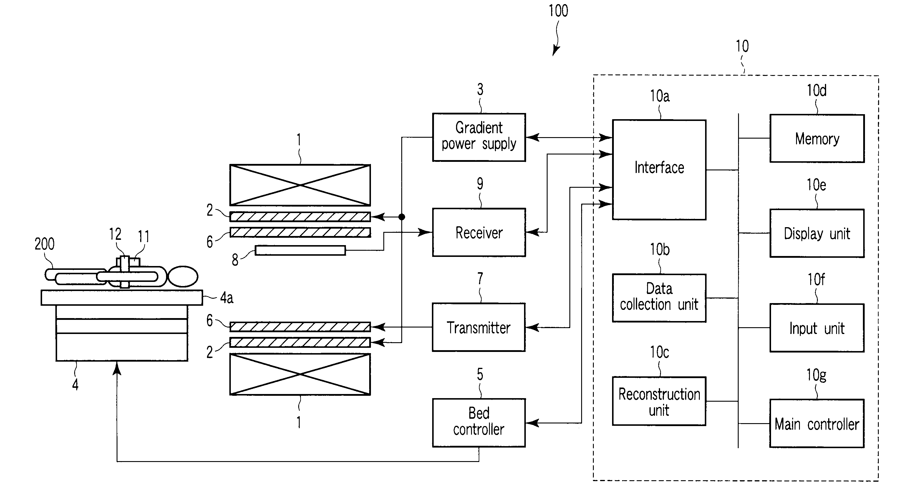
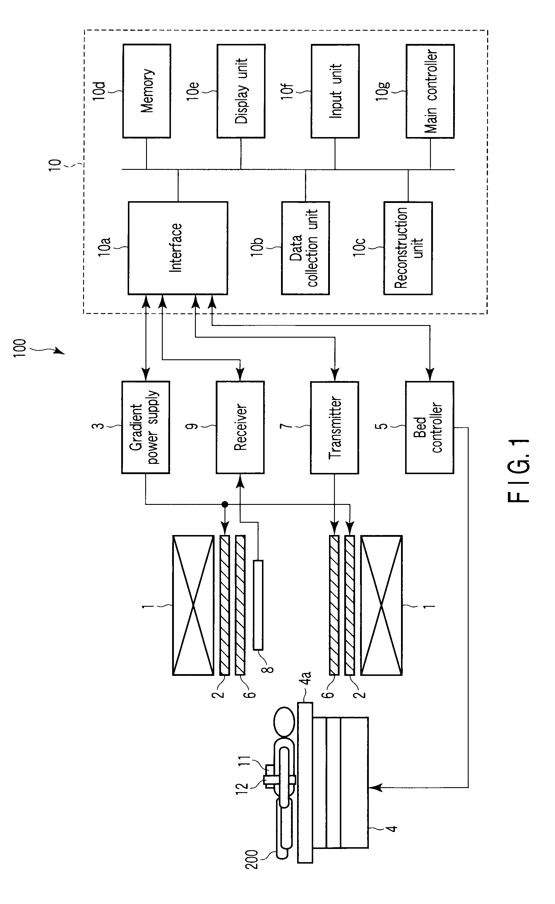
[0036]FIG. 1 shows the configuration of a magnetic resonance imaging (MRI) apparatus, generally indicated at 100, according to a first embodiment. The MRI apparatus 100 includes a static field magnet 1, a gradient coil 2, a gradient power supply 3, a bed 4, a bed controller 5, a transmission RF coil 6, a transmitter 7, a receiving RF coil 8, a receiver 9, a computer system 10, and a respiration suppressing member 11.
[0037]The static field magnet 1 is formed in the shape of a hollow cylinder and adapted to generate a uniform static magnetic field within its inside shape. As the static field magnet 1 use is made of a permanent magnet, a superconducting magnet, or the like.
[0038]The gradient coil 2 is formed in the shape of a hollow cylinder and placed inside the static field magnet 1. The gradient coil 2 is a combination of three coils each corresponding to a respective one of the three mutually orthogonal X, Y and Z axes. When the three coils are individually supplied with current fr...
second embodiment
[0065]The MRI apparatus according to a second embodiment is identical in configuration to the MRI apparatus 100 shown in FIG. 1. The MRI apparatus of the second embodiment is different from the MRI apparatus 100 in that a respiration suppressing member 13 is used in place of the respiration suppressing member 11.
[0066]FIG. 4A is a plan view of the respiration suppressing member 13. FIG. 4B is a side view of the respiration suppressing member 13. In FIGS. 3A and 3B, like reference numerals are used to denote corresponding parts to those in FIGS. 2A through 2D to thereby simplify the description.
[0067]As shown in FIGS. 4A and 4B, the respiration suppressing member 13 includes a rigid portion 11a, an elastic portion 11b, a cover 11c, a pressure sensor 13a, and a vibrator 13b. Though not shown in FIGS. 4A and 4B, the respiration suppressing member 13 further includes a drive circuit 13c as shown in FIG. 5. That is, the respiration suppressing member 13 is constructed such that the press...
third embodiment
[0073]The MRI apparatus according to a third embodiment is identical in configuration to the MRI apparatus 100 shown in FIG. 1. The MRI apparatus of the third embodiment is different from the MRI apparatus 100 in that a respiration suppressing member 14 is used in place of the respiration suppressing member 11.
[0074]FIG. 7A shows the respiration suppressing member 14 as viewed in the direction of the body axis of the subject 200. FIG. 7B shows the respiration suppressing member 14 as viewed from the side of the subject 200. In FIGS. 7A and 7B, like reference numerals are used to denote corresponding parts to those in FIGS. 2A through 2D or FIGS. 4A and 4B to thereby simplify the description.
[0075]As shown in FIGS. 7A and 7B, the respiration suppressing member 14 includes a rigid portion 11a, an elastic portion 11b, a cover 11c, a vibrator 13b, a bellows 14a, a tension generator 14b, and a tension sensor 14c. Though not shown in FIGS. 7A and 7B, the respiration suppressing member 14 ...
PUM
 Abstract
Description
Claims
Application Information