Methods and apparatus for adjusting a journal area for continuous data protection

a journal area and data protection technology, applied in the field of storage systems and data backup and recovery, can solve the problems of restoring the image of data, affecting the accuracy of data recovery,

Inactive Publication Date: 2008-08-21
HITACHI LTD
View PDF10 Cites 34 Cited by
  • Summary
  • Abstract
  • Description
  • Claims
  • Application Information

AI Technical Summary

Problems solved by technology

However, with the above method, it is only possible to restore the image of the data at the particular point in time at which the snapshot was taken.
Thus, restoring data from backup data taken only periodically may result in a loss of some amount of updates to the original data because there is a difference between the saved back up data and the data that is actually desired to be restored, such as the current data.
Further, for example, if the latest backup data has incorrect or corrupted actual data, it is ne

Method used


Image

  • Methods and apparatus for adjusting a journal area for continuous data protection
  • Methods and apparatus for adjusting a journal area for continuous data protection
  • Methods and apparatus for adjusting a journal area for continuous data protection

Examples


first embodiments

ion

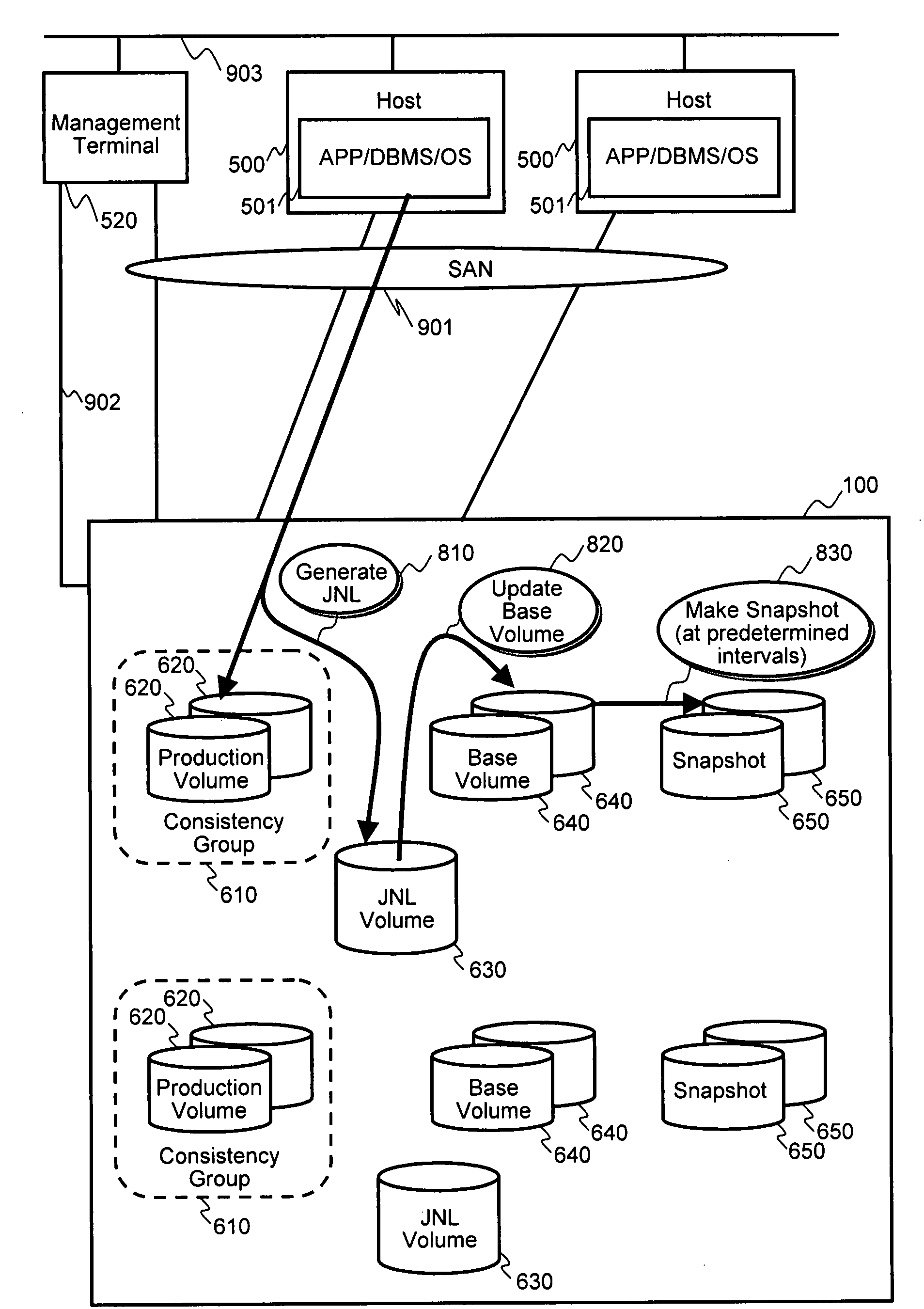
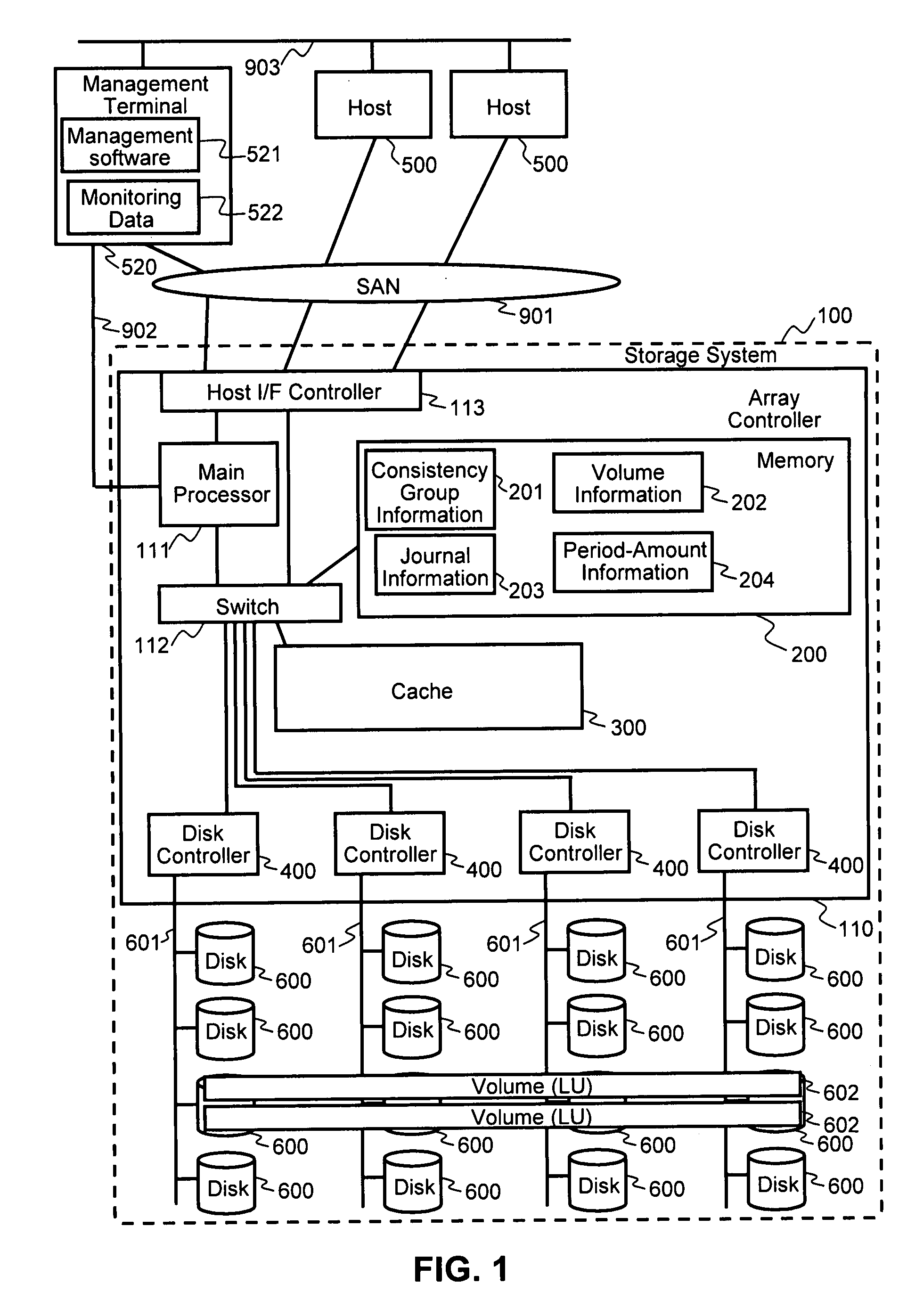
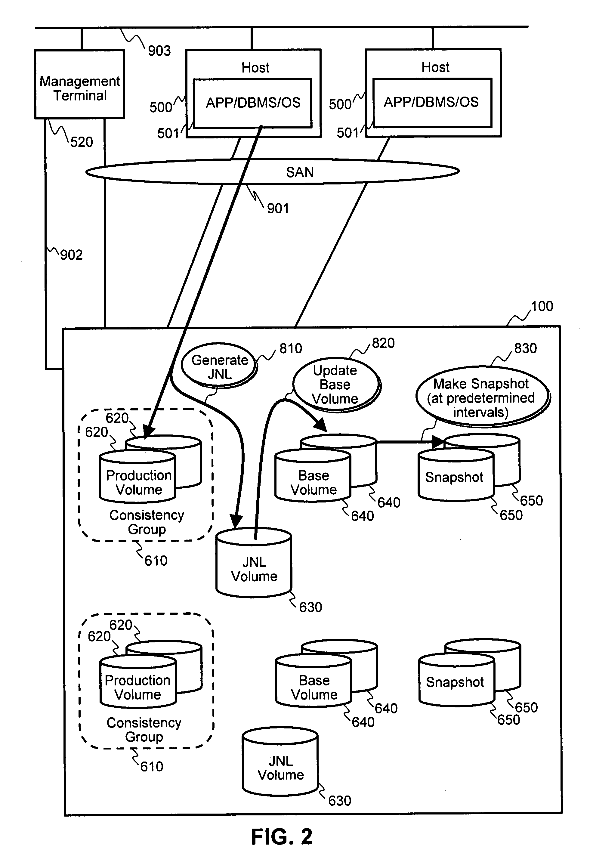
[0038]FIG. 1 describes and exemplary system and hardware configuration of an information system under which first embodiments of the invention may be practiced. A storage system 100 includes an array controller 110 for receiving data access commands from one or more host computers 500 via a network 901. Network 901 may be a storage area network (SAN), such as a Fibre Channel network, iSCSI(IP) or other network type or communications link enabling communications between hosts 500 and storage system 100.

[0039]Array controller 110 may include a main processor 111, a switch 112, one or more host interface (I / F) controllers 113, a system memory 200, a cache memory 300, and one or more disk controllers 400. Disk controllers 400 couple array controller 110 to one or more hard disk drives (HDDs) 600 via a backend path 601. Back end path 601 may be Fibre Channel, SATA, SAS, iSCSI(IP), or other suitable type of connection.

[0040]Main processor 111 performs various processes in array control...

second embodiments

on

[0082]FIG. 14 illustrates the system configuration of the second embodiments. The differences from the configuration of the first embodiments are that memory 200 includes chunk mapping information 205 and chunk usage information 206. In this configuration, storage areas provided by disks 600 are divided into a number of fixed-length storage area (i.e. chunks 690), and volumes (logical units) including journal volumes 630 are provided by allocating chunks of storage on demand. Moreover, in the second embodiments, as illustrated in FIG. 15, consistency group information 201 includes an additional preservation period field 2016, which retains information on a specified preservation period for journal data, as is discussed further below.

[0083]FIG. 16 illustrates a manner to provide volumes 602 in the storage system 100 of the second embodiment. In FIG. 16, a journal volume 630 is constituted by multiple segments 692 virtually, and one chunk 690 is assigned to one segment 692 as physic...

third embodiments

ting Journal

[0118]FIG. 23 illustrates a process of generating a journal in the third embodiments. The system configuration of the third embodiments may be the same as described above for the second embodiments. In the third embodiments, journal entries are able to be stored across chunks, such that a portion of a journal entry may be stored in a first chunk, and the remainder of the journal entry may be stored in a second chunk, thereby reducing wasted storage capacity. The process includes steps 1601-1609, as described below.

[0119]At step 1601, host 500 issues a write request and transfers write data to array controller 110.

[0120]At step 1602, array controller 110 stores the write data in production volume 620 according to the write request.

[0121]At step 1603, array controller 110 checks the remaining unused capacity (length) of the current chunk for containing metadata and the remaining unused capacity of the current chunk for containing journal data.

[0122]At step 1604, as a resul...


PUM


Abstract

In a storage system implementing journaling for data backup and restore, users are able to easily determine information regarding amounts journal data generated over specified periods of time. Flexible and automatic adjustment of the journal area is enabled by providing the user with the information on the relationships between the amounts of journal data generated over periods of time. Also dynamic allocation of storage capacity from free space may be applied to the journal volume on an as-needed basis, and may be used to minimize the size of the journal volume when certain journal entries are determined to be no longer needed. Thus, users are able to determine an appropriate size of a journal area in accordance with requirements for predetermined preservation periods for backup data. Thereby, management of the journal area is simplified and the costs to manage the journal area are reduced.

Description

BACKGROUND OF THE INVENTION[0001]1. Field of the Invention[0002]The present invention relates generally to storage systems and to backup and recovery of data.[0003]2. Description of Related Art[0004]A conventional method for achieving backup and recovery of data in storage systems is to backup the data periodically (e.g., once a day) from the storage system to a backup media, such as magnetic tapes. In creating the backup data, a snapshot of a storage area (e.g., a point-in-time copy of a volume) is often used to obtain data with consistency. That is, the data to be backed up is read from a snapshot volume (or a mirror image volume that has been split from a primary volume), and copied to the backup media. Several methods to provide a snapshot of a storage area logically or physically are well known in the prior art for storage systems. When it is necessary for data to be restored, the data saved to the backup media is read from the backup media, and may be written to a new storage ...

Claims


Application Information

Patent Timeline
IPC IPC(8): G06F12/00
CPCG06F11/1471G06F2201/855G06F11/2071G06F11/2064G06F2201/84
Inventor ARAKAWA, HIROSHIYAMAMOTO, AKIRA
Owner HITACHI LTD
Why Eureka
Try Eureka