
Self-cleaning filter arrangement with activation signal for floor care apparatus

a filter arrangement and self-cleaning technology, applied in the field of floor care, can solve the problems of unsatisfactory filter load, and achieve the effects of efficient and effective filter cleaning mechanism, long service life, and quick and easy operation

Inactive Publication Date: 2008-08-28
PANASONIC OF NORTH AMERICA
View PDF38 Cites 19 Cited by
  • Summary
  • Abstract
  • Description
  • Claims
  • Application Information

AI Technical Summary

Benefits of technology

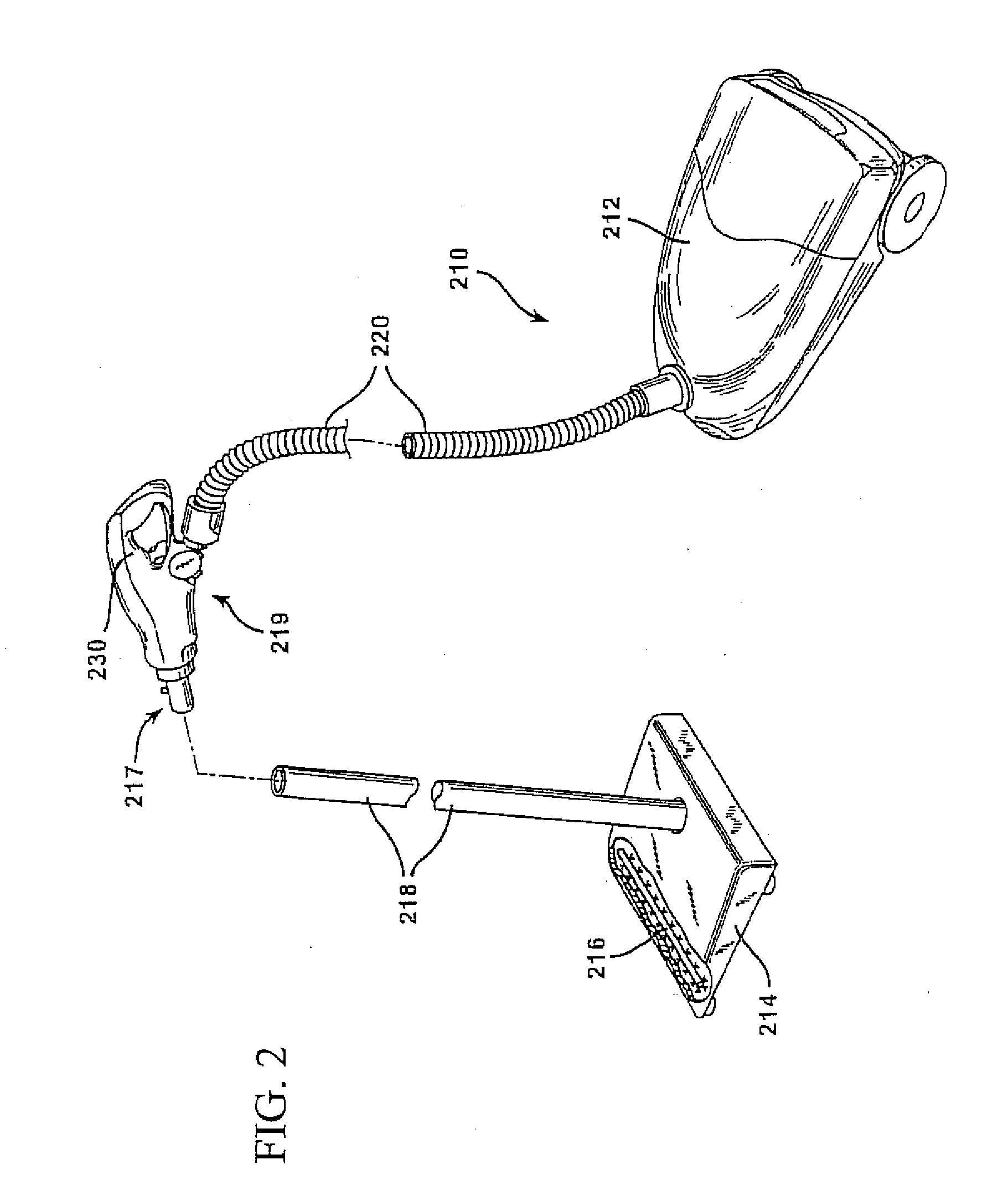
[0005]In accordance with the purposes of the present invention as described herein, an improved floor care apparatus is provided. The apparatus may take the form of a canister or an upright vacuum cleaner or may embody an extraction cleaning device or other hereinafter developed product. In this regard, the present invention relates to a vacuum cleaner, extractor or the like equipped with a more efficient and effective filter cleaning mechanism. Advantageously, the present invention allows for the quick and easy automatic cleaning of dirt and debris from a filter including particularly fine particles from the pores of the filter. As a result each filter has a longer service life and the apparatus may be operated at a higher cleaning efficiency over the entire length of that extended service life.
[0006]In one embodiment, a floor care apparatus has a filter with an intake and out take. A first pressure sensor is arranged on the intake while a second pressure sensor is arranged on the out take. A controller connects to the sensors to receive signals indicative of relative pressure. Whenever a predetermined pressure differential between the signals is achieved, an undesirable load on the filter is deemed having occurred and initiation of a self-cleaning of the filter begins. In this manner, filter cleaning only occurs on an as-needed basis and user intervention is avoided, thereby adding convenience. The controller is also able to ascertain a clogged airway condition. Various features contemplate pressure sensor signals arranged to scale suction as positive pressures, meeting the predetermined pressure differential at other than a maximum pressure differential between the first and second pressure sensors, and scaling the predetermined pressure differential relative to the maximum pressure differential.

Problems solved by technology

Whenever a predetermined pressure differential between the signals is achieved, an undesirable load on the filter is deemed having occurred and initiation of a self-cleaning of the filter begins.

Method used


Image

  • Self-cleaning filter arrangement with activation signal for floor care apparatus
  • Self-cleaning filter arrangement with activation signal for floor care apparatus
  • Self-cleaning filter arrangement with activation signal for floor care apparatus

Examples


Embodiment Construction

[0018]In the following detailed description of the illustrated embodiments, reference is made to the accompanying drawings that form a part hereof, and in which is shown by way of illustration, specific embodiments in which the invention may be practiced. These embodiments are described in sufficient detail to enable those skilled in the art to practice the invention and like numerals represent like details in the various figures. Also, it is to be understood that other embodiments may be utilized and that process, mechanical, electrical, arrangement, software and / or other changes may be made without departing from the scope of the present invention. In accordance with the present invention, methods and apparatus for self-cleaning floor care apparatus and attendant control, including activation signal are hereinafter described.

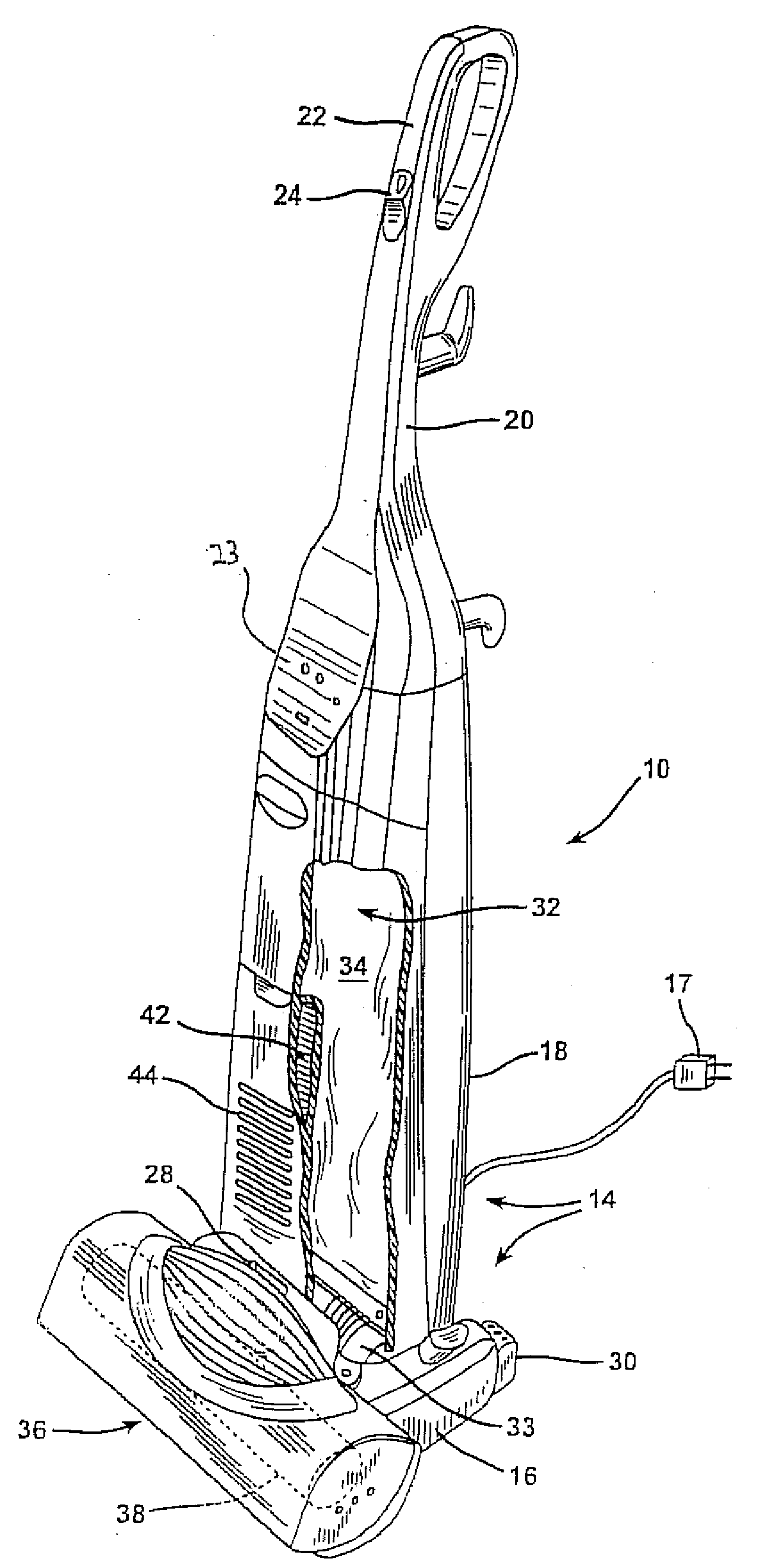
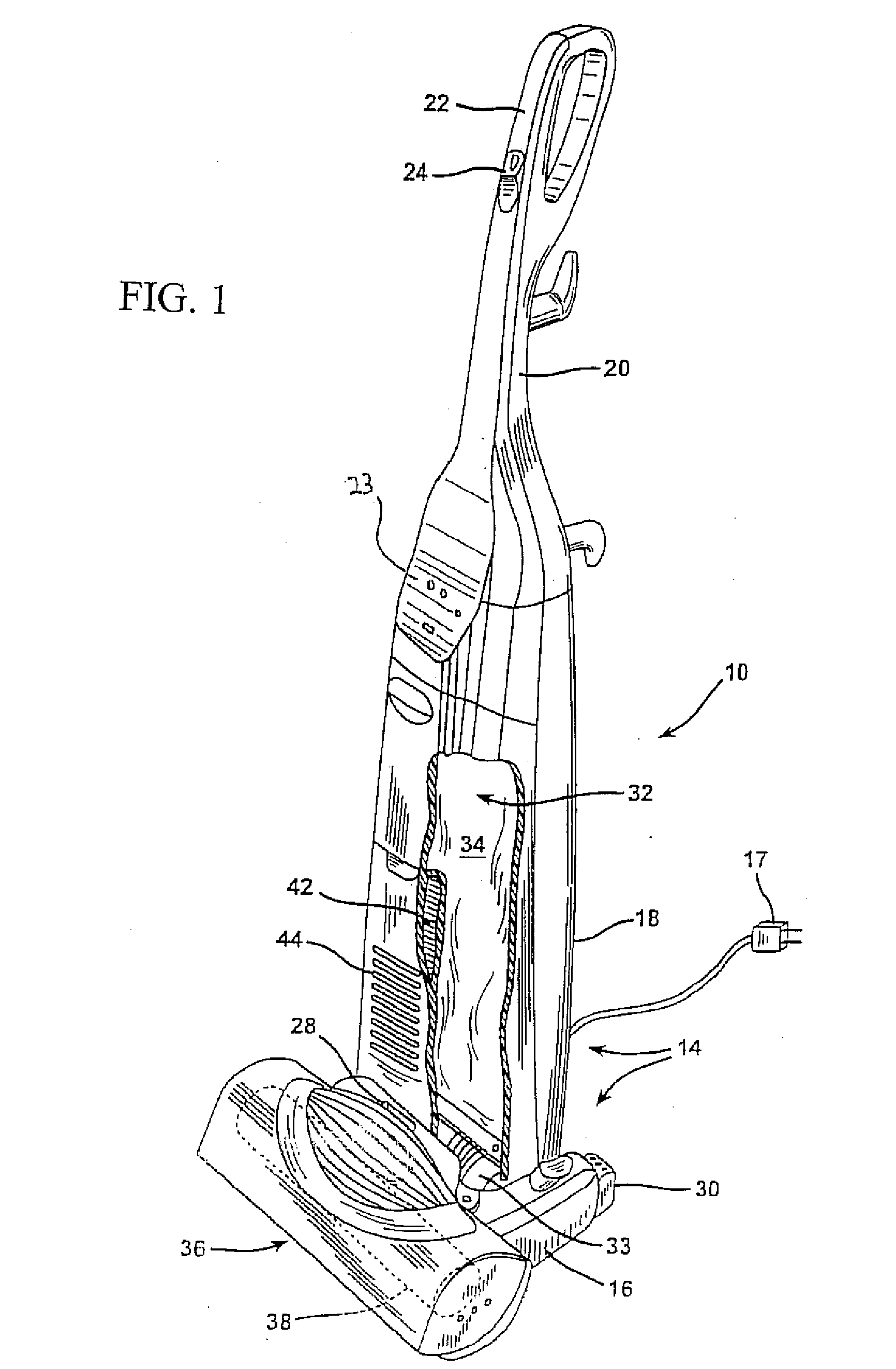
[0019]Reference is now made to FIG. 1 showing a floor care apparatus of the present invention. The apparatus illustrated exemplifies an upright vacuum cleaner...


PUM


Abstract

A floor care apparatus has a filter with an intake and out take. A first pressure sensor is arranged on the intake while a second pressure sensor is arranged on the out take. A controller connects to the sensors to receive signals indicative of relative pressure. Whenever a predetermined pressure differential between the signals is achieved, an undesirable load on the filter is deemed occurred and initiation of a self-cleaning of the filter begins. In this manner, filter cleaning only occurs on an as-needed basis and user intervention is avoided, thereby adding convenience. The controller is also able to ascertain a clogged airway condition. Various features contemplate pressure sensor signals arranged to scale suction as positive pressures, meeting the predetermined pressure differential at other than a maximum pressure differential between the first and second pressure sensors, and scaling the predetermined pressure differential relative to the maximum pressure differential.

Description

TECHNICAL FIELD[0001]The present invention relates generally to the floor care field. More particularly, it relates to a floor care apparatus, such as a canister or upright vacuum cleaner, having a self-cleaning filter and arrangement therefor. Particular aspects relate to activation of signals initiating self-cleaning, without user intervention, and doing so only on an as-needed basis.BACKGROUND OF THE INVENTION[0002]Whether canister or upright, vacuum cleaners in all of their designs and permutations have become increasingly popular over the years. In general, vacuum cleaners incorporate a suction fan motor, attendant dirt cup or dust bag and a nozzle assembly fluidly and mechanically connected to one another that suck up dirt and dust during operator movement across a dirt-laden floor. Specifically, an agitator within the nozzle assembly rotates to beat the nap of a carpet and dislodge dirt and dust during a time when an operator manipulates the cleaner back and forth. Dirt and d...

Claims


Application Information

Patent Timeline
IPC IPC(8): A47L9/10
CPCA47L9/20A47L9/2857A47L9/2821
Inventor CHARBONNEAU, GARY P.DEVER, KERRY L.
Owner PANASONIC OF NORTH AMERICA
Learn More