Electric hair clipper with automatic speed control

Inactive Publication Date: 2008-08-28
CONAIR CORP
View PDF13 Cites 4 Cited by
  • Summary
  • Abstract
  • Description
  • Claims
  • Application Information

AI Technical Summary

Benefits of technology

[0005]It is an object of the present invention to provide an improved hair clipper having a system that detects a load increase and that automatically and momentarily increases blade speed in response in order to more efficiently cut a more resistant section of hair.
[0007]The present invention achieves the above-mentioned objects by utilizing a control system in a hair clipper that senses increased load while operating and, as a result, automatically and momentarily increases blade speed output for more efficient cutting.

Problems solved by technology

When increased resistance is encountered, for example, when the blades pass from relatively thin hairs to hairs that are thicker or more difficult to cut, the corresponding increased load causes the motor to slow down and lose momentum.

Method used


Image

  • Electric hair clipper with automatic speed control
  • Electric hair clipper with automatic speed control
  • Electric hair clipper with automatic speed control

Examples


Embodiment Construction

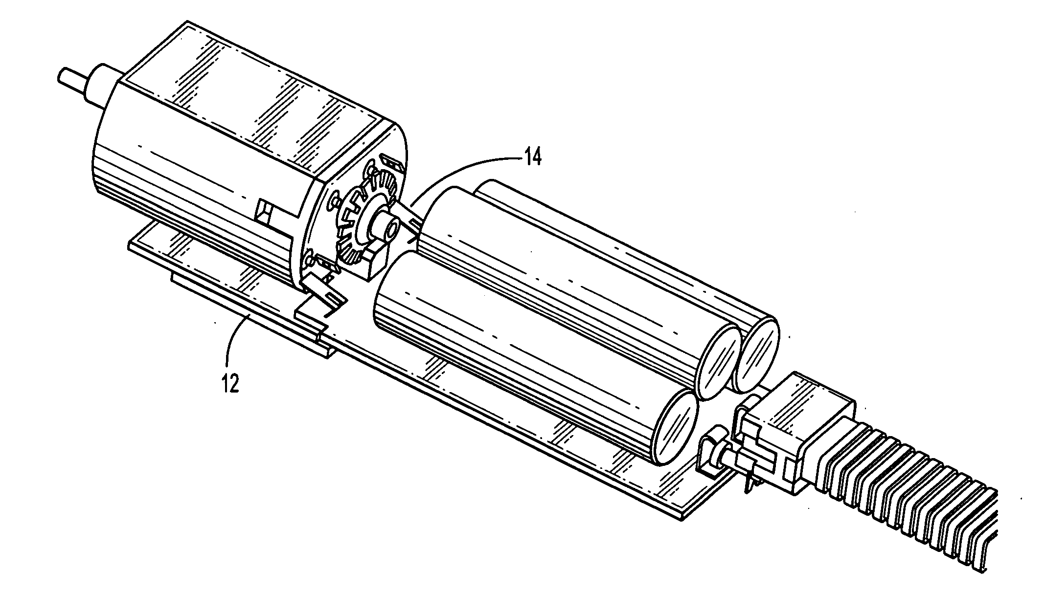
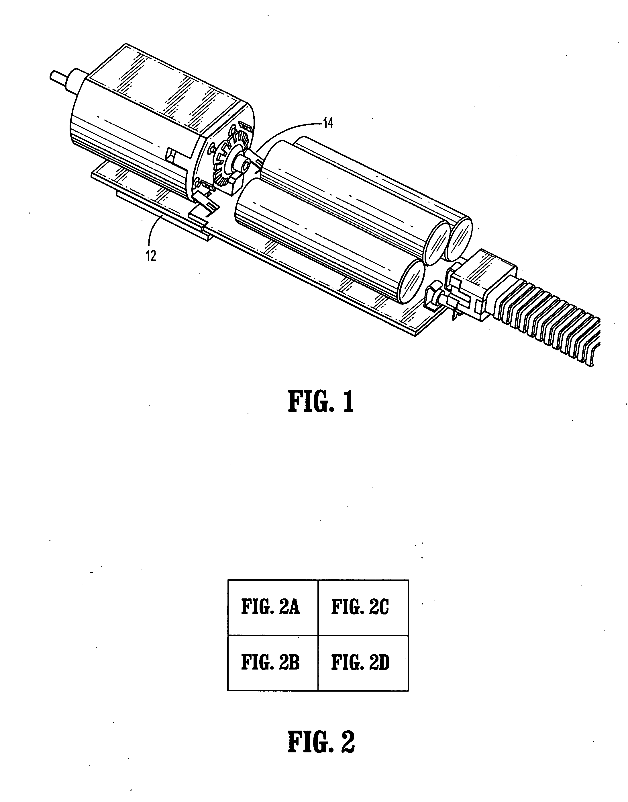
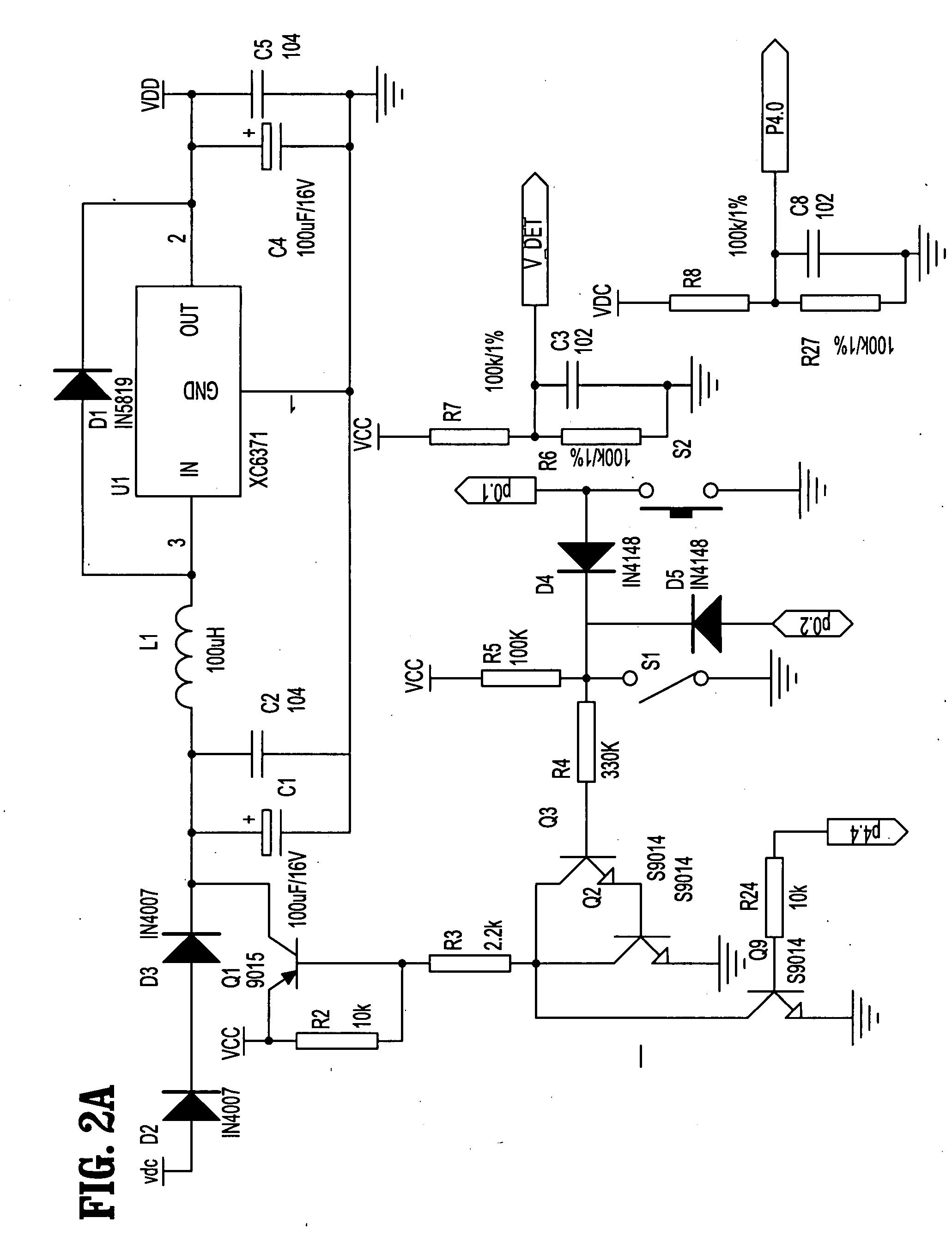
[0010]A conventional hair clipper (not shown) for cutting, shaving or trimming hair having conventional components is equipped with a control circuit (10) in order to achieve operation as set forth herein.

[0011]While the clipper is operating at a predetermined, constant motor speed and, thus, the blades are also moving at a relatively constant speed, a user moves the blades across an area of hair to be cut. A photoelectric cell (12) is arranged as is known to those skilled in the art to measure the motor's rotational speed and transmit corresponding data to a microprocessor (not shown). A photoelectric switch associated with the cell (12) reads signals from a component mounted on the motor axis (14).

[0012]If, while operating at a normal speed, the user moves to a more cut-resistant section of hair, motor speed will decrease. This change in speed is detected by the cell (12) and microprocessor. The microprocessor then accordingly adjusts the pulse width modulation of the motor to inc...


PUM


Abstract

A control system (10) in a hair clipper that senses increased load while operating and, as a result, automatically and momentarily increases blade speed output for more efficient cutting.

Description

CROSS-REFERENCE TO RELATED APPLICATIONS[0001]None.TECHNICAL FIELD[0002]The present invention relates to electric hair clippers for shaving and cutting hair and, more particularly, to hair clippers having components and circuitry designed to sense a load increase while operating and, in response to such load increase, to increase operating speed of the blades to more efficiently cut or shave hair causing the load increase.BACKGROUND OF THE INVENTION[0003]Known clippers for shaving, cutting and trimming hair typically operate at a constant speed. This is true whether or not the clipper is a one-speed unit or has multiple speed settings. When increased resistance is encountered, for example, when the blades pass from relatively thin hairs to hairs that are thicker or more difficult to cut, the corresponding increased load causes the motor to slow down and lose momentum.[0004]Known electric motorized devices include motor speed feedback systems that can sense load or output speed and, r...

Claims


Application Information

Patent Timeline
IPC IPC(8): B26B19/00
CPCB26B19/04B26B19/388B26B19/38B26B19/06
Inventor LEUNG, ANTHONY KIT LUN
Owner CONAIR CORP
Why Eureka
Try Eureka