Method and device for cutting tubular glass, and method for manufacturing tubular glass

Inactive Publication Date: 2018-08-02
NIPPON ELECTRIC GLASS CO LTD
View PDF0 Cites 7 Cited by
  • Summary
  • Abstract
  • Description
  • Claims
  • Application Information

AI Technical Summary

Benefits of technology

[0023]According to the present invention, the tube glass can be

Problems solved by technology

Specifically, the cutting blade is brought into contact with the tube glass under a state in which the cutting blade is cooled by water or the

Method used


Image

  • Method and device for cutting tubular glass, and method for manufacturing tubular glass
  • Method and device for cutting tubular glass, and method for manufacturing tubular glass
  • Method and device for cutting tubular glass, and method for manufacturing tubular glass

Examples


first embodiment

[0047]Now, description is made of embodiments of the present invention with reference to the drawings. FIG. 1 to FIG. 17 are illustrations of a cutting method for a tube glass, a cutting device for a tube glass, and a manufacturing method for a tube glass product according to the present invention.

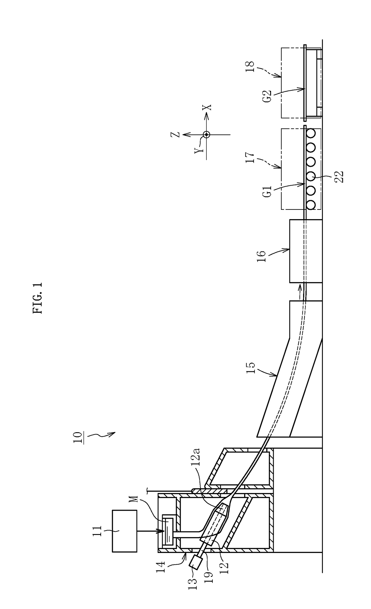
[0048]FIG. 1 is an illustration of one example of a manufacturing apparatus 10 for a tube glass product to which the present invention is applicable. The manufacturing apparatus 10 is configured to form a continuous tube glass G1 by a Danner method, and mainly comprises a glass melting furnace 11, a sleeve 12, a drive device 13, a muffle furnace 14, an annealer 15, a tube drawing device 16, a cutting device (hereinafter referred to as “first cutting device”) 17, and a cutting device (hereinafter referred to as “second cutting device”) 18. The drive device 13 is configured to drive the sleeve 12 to rotate. The muffle furnace 14 is configured to accommodate the sleeve 12. The tube drawing de...


PUM


Abstract

Provided is a cutting method for a tube glass, including: a heating step of heating a preset cut portion (CP) of the tube glass (G2) by radiating laser light (L11) to the preset cut portion (CP); an inner crack region forming step of forming an inner crack region (C1) including one or a plurality of cracks through multiphoton absorption that occurs in an irradiation region of laser light (L12) by radiating the laser light (L12) having a focal point adjusted to an inside of the preset cut portion (CP); and a cooling step of cooling the preset cut portion (CP), to thereby cause the cracks to propagate in the inside of the preset cut portion (CP).

Description

TECHNICAL FIELD[0001]The present invention relates to a cutting method for a tube glass, a cutting device for a tube glass, and a manufacturing method for a tube glass product.BACKGROUND ART[0002]A tube glass product used in, for example, a medical ampule, a medical syringe, and a fluorescent tube for lighting is formed by various methods such as a Danner method and a down-draw method. Description is made of the overview of the Danner method below as an example.[0003]When a tube glass product is manufactured by the Danner method, molten glass is first supplied to a rotatable sleeve arranged in a muffle furnace. The supplied molten glass is formed into a tube shape while being wound on an inside of the sleeve. The molten glass formed into a tube shape is pulled out from a distal end of the sleeve by a tube drawing device (pulling device) to form a tube glass continuously (for example, see Patent Literature 1).[0004]The tube glass having been continuously formed (hereinafter referred ...

Claims


Application Information

Patent Timeline
IPC IPC(8): C03B33/10B23K26/53C03B33/095B26D3/16C03B33/06
CPCC03B33/102B23K26/53C03B33/095B26D3/16C03B33/06C03C25/70B28D5/00B23K26/0006B23K26/0823B23K26/0838C03B33/0955C03B35/26C03B17/025B23K26/703B23K26/082B23K26/0624B23K26/60B23K2103/54B23K2101/06B28D1/221B28D7/02C03B33/0222
Inventor WADA, MASANORIIWASAKI, TAKANORI
Owner NIPPON ELECTRIC GLASS CO LTD
Why Eureka
Try Eureka