Pneumatic Servobrake and Diaphragm Therefor

Active Publication Date: 2008-08-28
CONTINENTAL TEVES AG & CO OHG
View PDF2 Cites 1 Cited by
  • Summary
  • Abstract
  • Description
  • Claims
  • Application Information

AI Technical Summary

Benefits of technology

[0013]A favorable embodiment of the invention provides that the rib structure with ribs and rib gaps is provided on a radial inside surface of the sealing bead and on a radial outside surface, whereby even deformation of the sealing bead results. The ribs can be arranged on the radial inside surface and the radial outside surface so as to be offset relative to each other, or they can be arranged opposite each other according to another favorable embodiment. The last mentioned embodiment involves the special advantage that the sealing bead despite ribs ha

Problems solved by technology

Tests have shown that the displacement of the excess sealing bead volume will deteriorate the assembly of the diaphragm, and

Method used


Image

  • Pneumatic Servobrake and Diaphragm Therefor
  • Pneumatic Servobrake and Diaphragm Therefor
  • Pneumatic Servobrake and Diaphragm Therefor

Examples


second embodiment

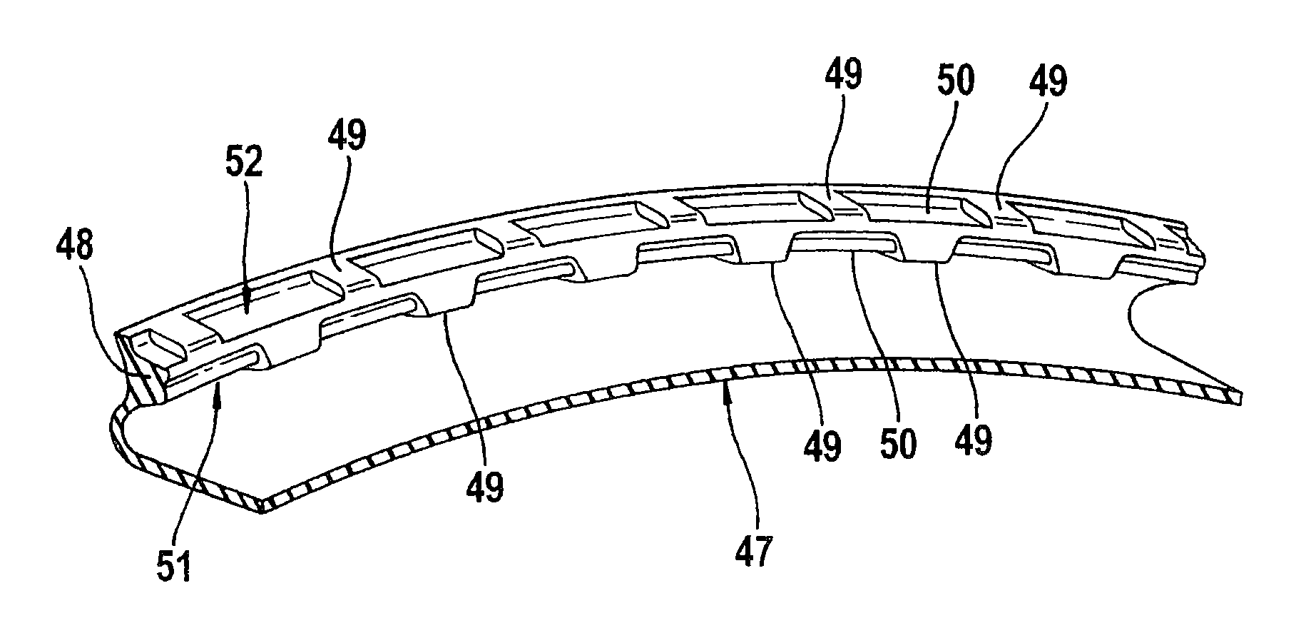
[0041]FIG. 3 is a three-dimensional view of a cutout of a diaphragm 47 of a It can be seen that the diaphragm 47 can include a radially outward sealing bead 48 with ribs 49 and rib gaps 50, and the ribs 49 and ribs gaps 50 are provided in each case offset relative to one another at a radial inside surface 51 and a radial outside surface 52. In this embodiment, too, the inside surface 51 and the outside surface 52 can have a slightly conical design in order to facilitate the assembly of the diaphragm 47. In addition, the ribs 49 can have insertion ramps for this purpose.

third embodiment

[0042]FIGS. 4a and 4b depict a third embodiment, whose diaphragm 53 includes a radially outward sealing bead 54 with a circumferential rib structure, i.e. ribs 55 and rib gaps 56. As becomes apparent from FIG. 4a in particular, the ribs 55 and the rib gaps 56 are respectively arranged opposite each other at a radial inside surface 57 and a radial outside surface 58. Furthermore, the inside surface 57 and the outside surface 58 can have a slightly conical design or include insertion ramps 59 for improving the assembly, as has been described hereinabove with regard to the first two embodiments.

[0043]Especially the third embodiment of the brake booster with ribs 55 lying on top of each other has proved particularly favorable in terms of stabilizing the sealing bead 54, the rib structure safeguarding a correct seat of the sealing bead 54 in the mounting space 37 after the housing shells 2, 3 have been joined, since the opposite ribs 55 properly stabilize the sealing bead 54 in spite of ...


PUM


Abstract

A pneumatic brake booster with a booster housing, which comprises a first and a second housing shell and is subdivided into a working chamber and a vacuum chamber by an axially movable wall to which a pneumatic differential pressure can be applied, with the movable wall being formed of a diaphragm plate and a diaphragm abutting thereon that includes a radially inward sealing bead and a radially outward sealing bead for sealing the two chambers and the radially outward sealing bead is compressible between the housing shells. To improve the compression of the radially outward sealing bead, the radially outward sealing bead has a circumferential, uniform rib structure.

Description

[0001]This application is the U.S. national phase application of PCT International Application No. PCT / EP2006 / 064500, filed Jul. 21, 2006, which claims priority to German Patent Application No. DE102005034959.5, filed Jul. 22, 2005 and German Patent Application No. DE102005061353.5, filed Dec. 21, 2005, the contents of such applications being incorporated by reference herein.BACKGROUND OF THE INVENTION[0002]1. Field of the Invention[0003]The present invention relates to a pneumatic brake booster with a booster housing, which comprises a first and a second housing shell and is subdivided into a working chamber and a vacuum chamber by an axially movable wall to which a pneumatic differential pressure can be applied, with the movable wall being formed of a diaphragm plate and a diaphragm abutting thereon that includes a radially inward sealing bead and a radially outward sealing bead for sealing the two chambers, and the radially outward sealing bead is compressible between the housing...

Claims


Application Information

Patent Timeline
IPC IPC(8): F15B9/10
CPCF16J3/02B60T13/569
Inventor FALLER, JURGENJAKOBI, RALF
Owner CONTINENTAL TEVES AG & CO OHG
Why Eureka
Try Eureka