Fiber strip splicer for taping machines

a fiber strip and taping machine technology, applied in the field of synthetic fiber strip application, can solve the problems of limiting the productivity of the machine, and achieve the effect of reducing the cost of splicing and splicing

Inactive Publication Date: 2008-08-28
TORRES MARTINEZ MANUEL
View PDF6 Cites 7 Cited by
  • Summary
  • Abstract
  • Description
  • Claims
  • Application Information

AI Technical Summary

Benefits of technology

[0010]According to the invention, an automatic splicer for joining fiber strips is proposed, whereby the downtime for replacing fiber strip feed reels in machines for applying said strips is virtually eliminated.
[0012]Said arrangement allows the fiber strip which is being supplied to the application process to pass freely through the splicer, and allows preparing the fiber strip of a new feed reel in a standby position without interrupting said supply, such that when the reel of the fiber strip which is being supplied ends, the splicer automatically joins the fiber strip of the reel on standby with the fiber strip of the reel that is ending, the splicing being carried out in a very short time (about 2 seconds), therefore stopping the machine for that purpose has virtually no effect on productivity.
[0015]At the front of the modules, between which the fiber strips to be joined are caught, there are mutual insertion conformations by means of a recess in one of the modules and a corresponding projection in the other module, such that when the pressure for joining the fiber strips is applied, the assembly of such strips is located inside said insertion, thus preventing the width from being altered by the effect of the pressure for the purpose of maintaining the suitable conditions for the application, because it is critical for the width of the assembly of the supplied fiber strip to be uniform for this purpose.

Problems solved by technology

However, in a high performance machine it may be necessary to change the reels every five or ten minutes, each reel change requiring, by means of the manual process, a machine downtime of the same order, which conditions idle times that considerably limit the productivity of the machines.

Method used


Image

  • Fiber strip splicer for taping machines
  • Fiber strip splicer for taping machines
  • Fiber strip splicer for taping machines

Examples


Embodiment Construction

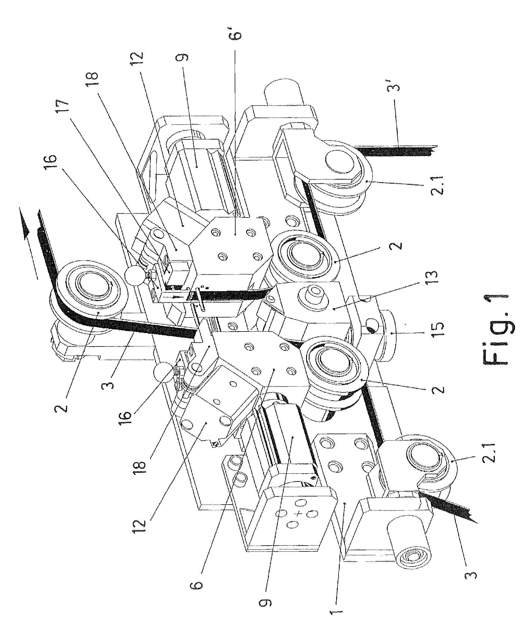
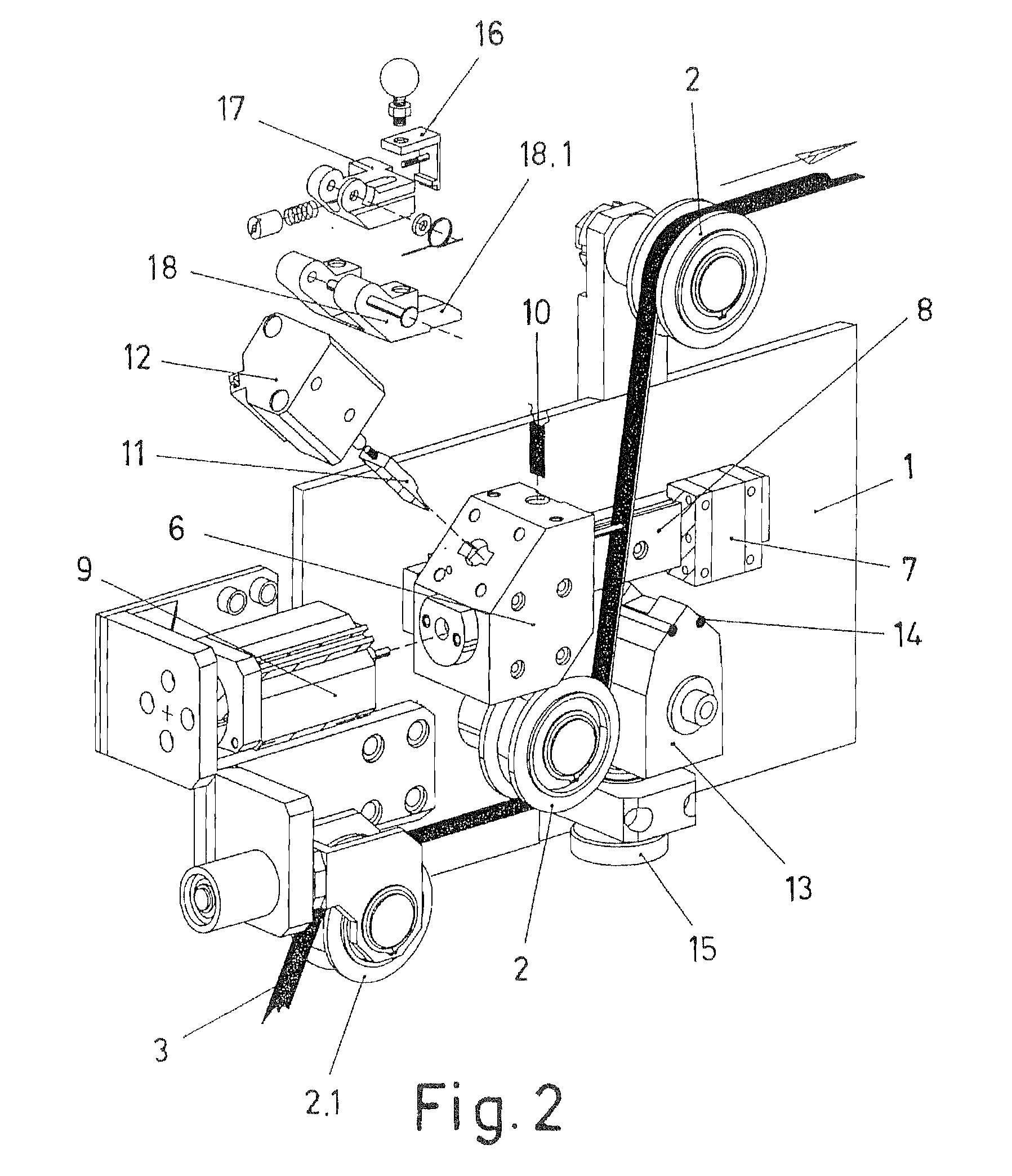
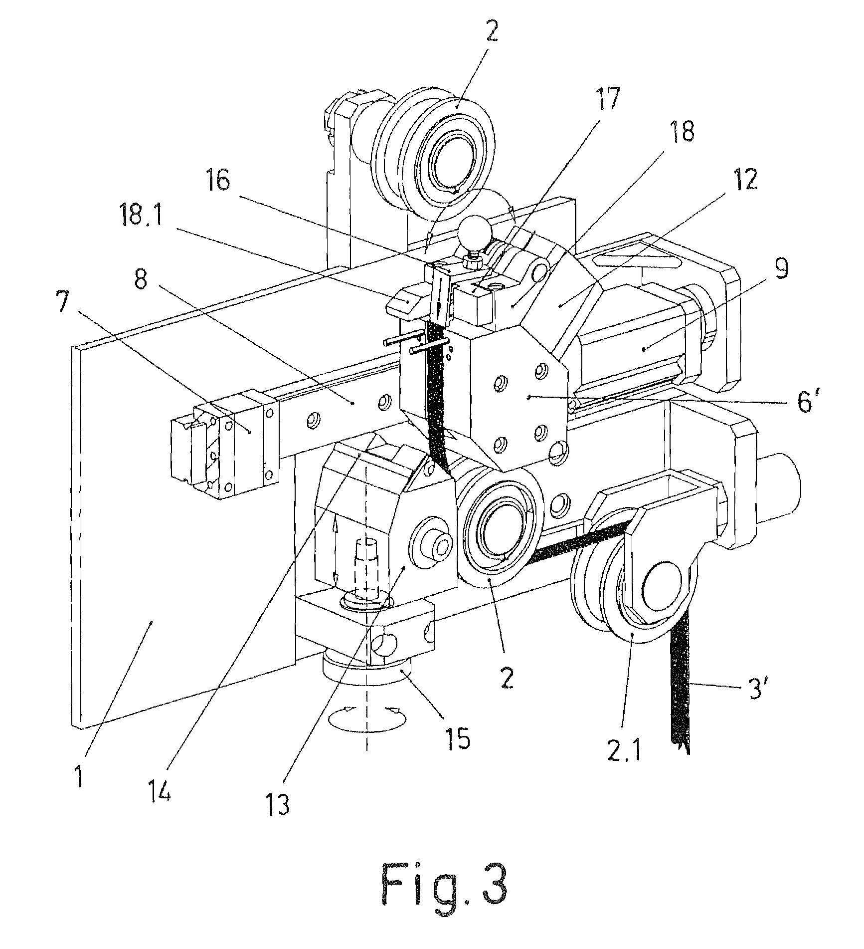
[0027]The object of the invention relates to a splicer intended to automatically join fiber strips in processes for manufacturing parts by taping by means of applying said fiber strips, for the purpose of establishing the continuity of the fiber strip feed supply to the application processes by means of joining the fiber strip coming from a feed reel that is ending and the fiber strip of a new reel continuing the supply.

[0028]The proposed splicer structurally consists of a frame (1) on which there are joined pulleys (2) driving the fiber strips in a circulation passage towards the application process thereof.

[0029]The path of the fiber strips towards the circulation passage through the splicer is formed from two feed supply directions, for the path for the passage of respective fiber strips (3, 3′) coming from respective feed reels (4, 4′) which can be independently arranged on respective shafts (5, 5′).

[0030]At the entrance of the path of the fiber strips (3, 3′) to the splicer, fr...


PUM

PropertyMeasurementUnit
timeaaaaaaaaaa
pressureaaaaaaaaaa
areaaaaaaaaaaa

Abstract

The invention relates to a fiber strip splicer for taping machines, formed by two mobile assemblies comprising respective modules (6, 6′) between which the capture for joining the fiber strip (3) that is being fed to the application process and a strip (3′) intended to continue with the supply when the first strip ends is possible, the modules (6, 6′) incorporating heating means (10) to activate the fiber strips in the joining, a blade for cutting the excess of the finished fiber strip (3) after the joint, and a catch (16) for securing the end of the new fiber strip (3′) on standby for the joining.

Description

FIELD OF THE ART [0001]The present invention relates to the application of synthetic fiber strips by means of taping machines on surfaces or jigs with the geometry of the parts to be manufactured, and particularly to the application of individual fiber strips by means of an applicator head for applying multiple strips at the same time from respective feed reels, proposing a splicer for automatically joining the strip coming from a reel that is ending and the strip coming from a new feed reel.STATE OF THE ART [0002]The industry for manufacturing parts formed by synthetic fibers, such as carbon fiber or glass fiber, is applied to produce increasingly larger parts and in larger amounts. This requires adapting the productivity of the taping machines with which the fiber material is applied.[0003]To that end, machines have been developed with applicator heads simultaneously applying multiple fiber strips, forming application webs reducing the necessary number of runs and therefore the ti...

Claims


Application Information

Patent Timeline
Patent Type & Authority Applications(United States)
IPC IPC(8): B65H69/06
CPCB29C65/18B29C66/1122B29C66/43B29C66/80B29C66/919B29C66/929B29C66/9241B65H69/08B65H2701/37B29C65/305B29C66/81427B29C66/91411B29C66/81431B29L2007/007B29C66/8242B29C66/8244B29C66/83221
Inventor TORRES MARTINEZ, MANUEL
Owner TORRES MARTINEZ MANUEL
Why Eureka
Try Eureka