Manhole cover extractor

US20110133140A1Inactive Publication Date: 2011-06-09SHEPHERD ALAN BYRON

Image

  • Manhole cover extractor
  • Manhole cover extractor
  • Manhole cover extractor

Examples


Embodiment Construction

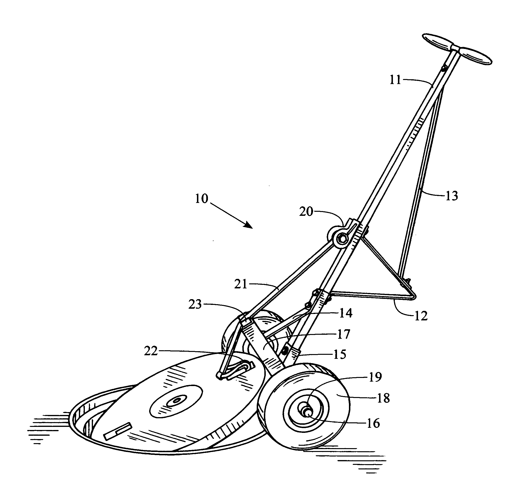
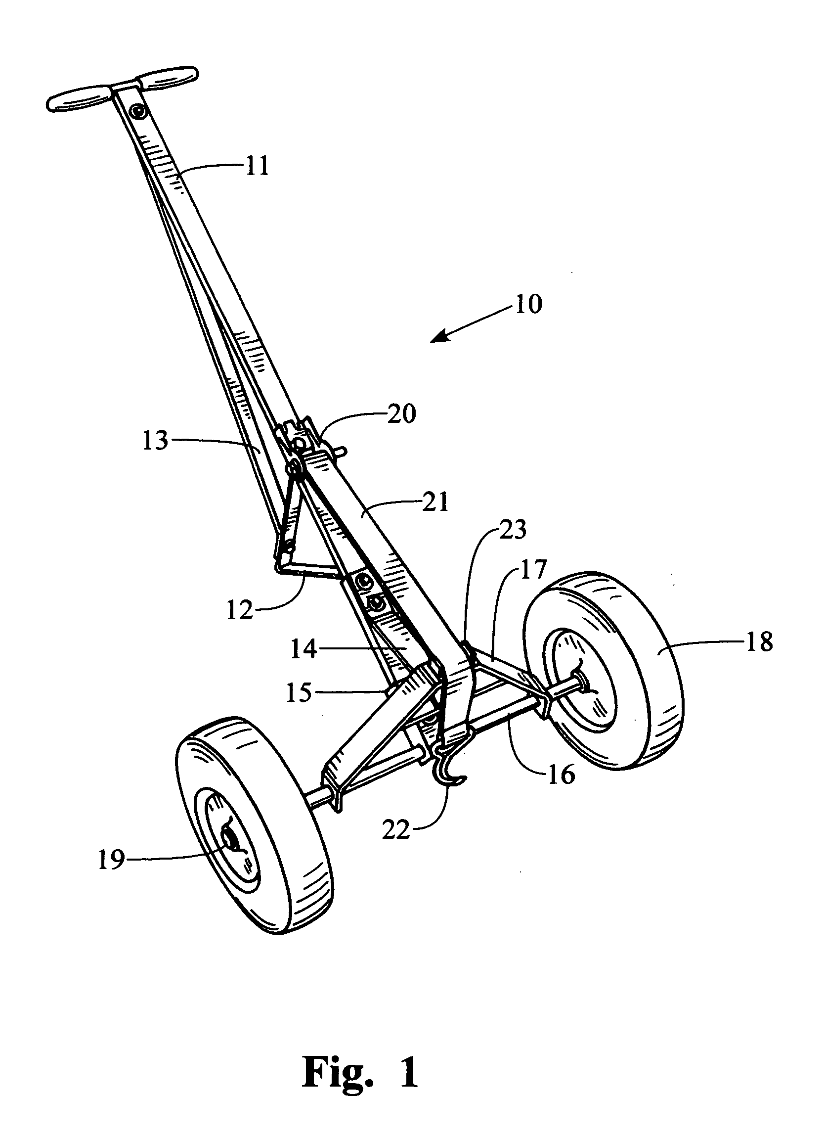
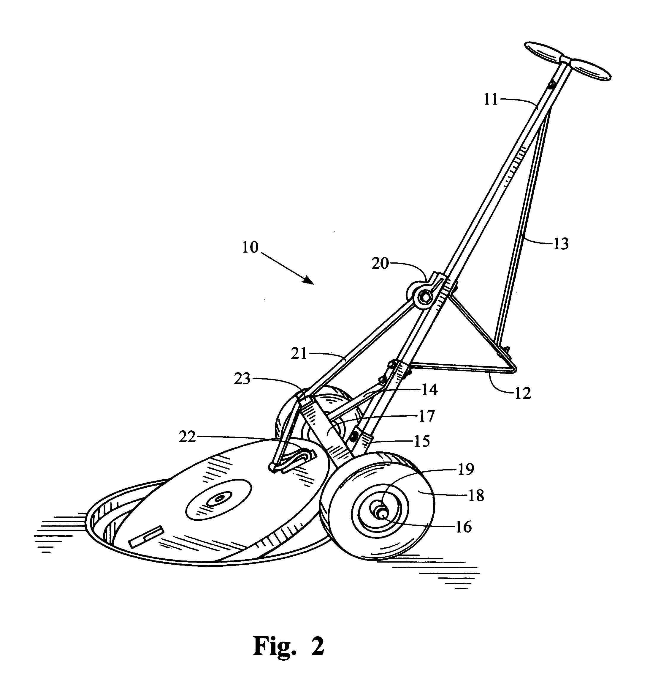
[0017]FIG. 1 shows a top sectional view of the best mode Contemplated by the inventor of the manhole cover and handhole enclosure cover extractor 10 according to the concepts of the present invention. As can be amply seen from the drawings the manhole cover and handhole cover extractor 10 and includes the referenced T-bar assembly 11 made of a thin wall channel tubing consisting of welded handles and rubber grips for secure handling, giving the extractor the fulcrum for popping and consequently movement of covers. The T-bar sits inclined from stand 12 which acts as gusset as is 13 giving the T-bar rigidity, both 12 and 13 are bolted to T-bar. A stiffening bar 14 is bolted to the T-bar 11 giving inflexibility to lower unit 15 which is through bolted to T-bar 11.

[0018]Lower unit 15 is a U channel that incorporates the axle 16 that is welded and the A frame 17 which is welded to axle 16. Lower unit 15 is subsequently bolted from A-frame 17 through stiffening bar 14 that is through bolt...


PUM


Abstract

A manhole cover extractor that pulls and lifts weighty horizontal items such as manhole covers and handhold enclosure covers that are lifted perpendicular from one side and pulled from the original position, removed and on same plane able to lift and move cover back to the original setting or simply move cover as to not create a tripping hazard; the tool consists of a T-bar which gives the necessary fulcrum for effortless removal and management of cumbersome manhole covers, the T-bar is comprised with handles to control the load. A polypropylene strap which is doubled back with reinforced cross stitching and J-hook which engages the object(s) listed and the aforementioned polypropylene strap is docked to the T-bar handle. Pneumatic all-terrain tires that are attached to an axle that is secured to the T-bar handle through the A-frame of the dolly.

Description

CROSS REFERENCE TO RELATED APPLICATIONS[0001]This application is a Division of Application Ser. No. 61 / 267,022 filed on Dec. 5, 2009. This application claims Priority of Patent Application Ser. No. 61 / 267,022 filed on Dec. 5, 2009.STATEMENT REGARDING FEDERALLY SPONSORED R & D[0002]NOT APPLICABLENAMES OF PARTIES TO A JOINT RESEARCH AGREEMENT[0003]NOT APPLICABLEBACKGROUND OF THE INVENTION[0004]1. Field of the Invention[0005]The present invention relates to an extraction tool for removal of manhole covers and handhold enclosure covers up to 18 inches in width. This hand tool simply lifts one side perpendicularly from the original seat through foot pressure at the axle for stability and a pulling motion towards the operator of the extractor, by means of T-bar handles and with minimal effort lifts cover and able to remove cover from working area, consequently not creating a tripping hazard in the region of the newly created hole. To reinstall movement of the cover is relatively the same ...

Claims


Application Information

Patent Timeline
09 Jun 2011
Publication
US20110133140A1
IPC
B66F11/00; B62D1/04; B66F3/00
CPC
B62B1/06; B66F19/005; B62B5/0089
Inventors
SHEPHERD, ALAN BYRON