Method and apparatus for forming modules from harvested crops

a technology of modules and harvesters, applied in the field of systems and methods for forming modules from harvested crops, can solve the problems of inability to quickly and efficiently dispose of loose harvested cotton from harvester enclosures, inability to quickly and efficiently store and handle loose cotton,

Inactive Publication Date: 2008-05-13
LACKEY WELDON LEROY
View PDF8 Cites 6 Cited by
  • Summary
  • Abstract
  • Description
  • Claims
  • Application Information

AI Technical Summary

Problems solved by technology

Although some six-row and eight-row cotton harvesting systems are emerging, they are not successful on a large scale.
They too typically have the problems common to four-row harvesting systems, e.g., the inability to quickly and efficiently dispose of the loose harvested cotton from harvester enclosures.
Cotton in loose form is difficult to store and handle efficiently.
Attempts at creating commercially available methods of moving the loose cotton from the harvester enclosures directly to compacted cotton have met with limited success.
This bottleneck creates a variety of problems that hinders the speed of harvest and has inadvertently stagnated further development in this particular area.
Building modules in this fashion generally results in modules of uneven density.
Such modules are more susceptible to breakage during handling and storage than modules of uniform sufficient density.
In addition, top-built modules typically require a finishing compaction cycle.
The finishing compaction cycle, along with the time typically required to move and then set up the module builder again, contributes to inefficiency in the harvesting and compaction process.
Other drawbacks shared by typical top-built module builders become evident in the filling cycles of these machines.
This close proximity to the module builder, or transfer receptacle, impedes the harvester from being equ

Method used


Image

  • Method and apparatus for forming modules from harvested crops
  • Method and apparatus for forming modules from harvested crops
  • Method and apparatus for forming modules from harvested crops

Examples


Embodiment Construction

[0019]Preferred embodiments of the present invention include both an apparatus and method for modulating cotton.

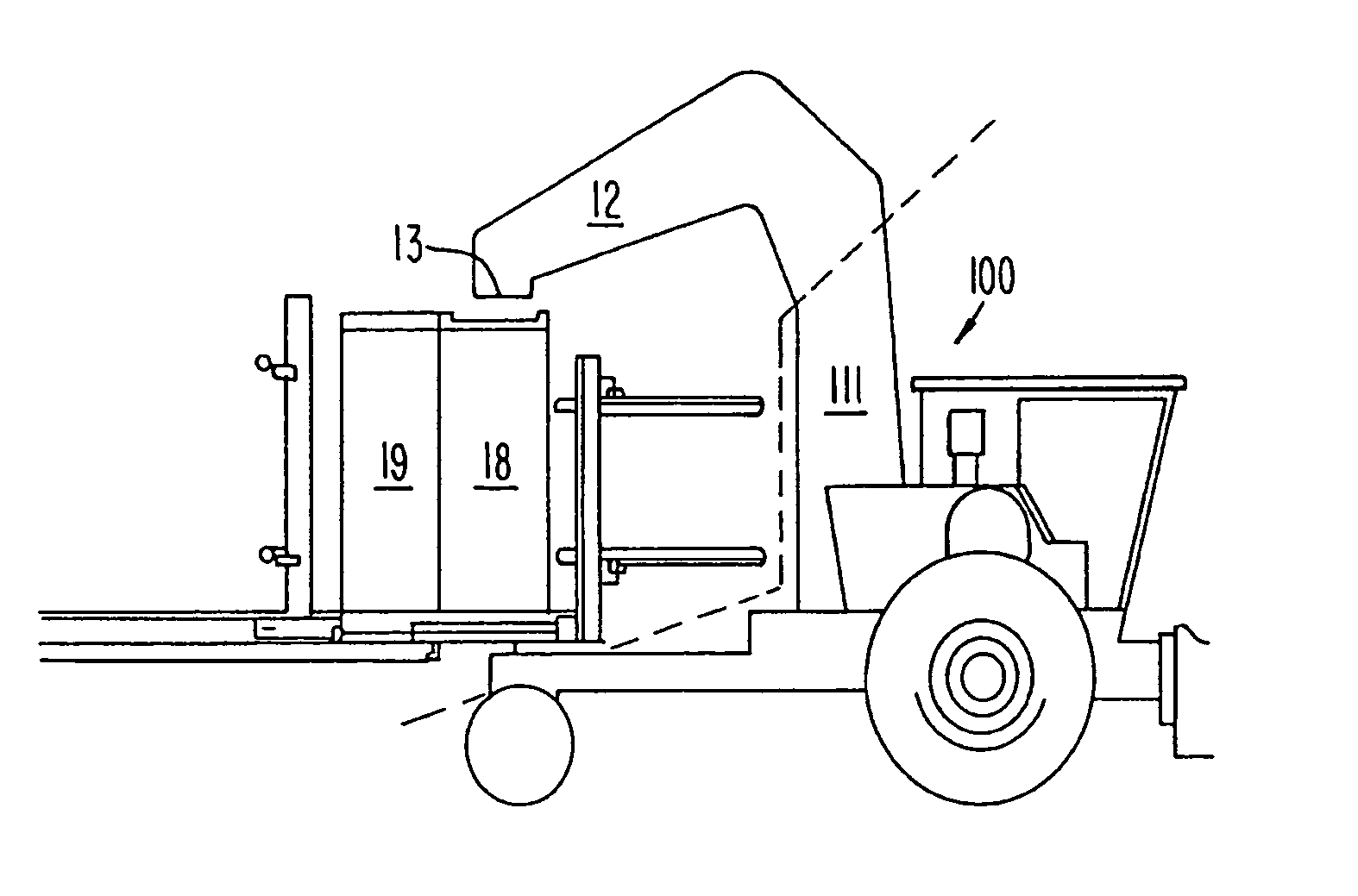
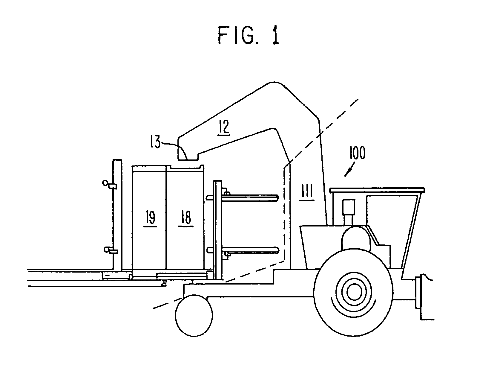
[0020]FIG. 1 is a side view of an apparatus of the present invention used within a harvesting system to enhance the speed and efficiency with which cotton can be harvested. Preferred embodiments of the present invention include a holding chamber 12. The holding chamber 12 is attached to a harvester 100 in a manner that allows harvested material to be collected and then gravity fed through a door 13 at one end of the chamber 12. The door 13 is positioned above a compression chamber 18 that, in preferred embodiments, sits substantially centered on the pivot point of the wheeled main frame. In some embodiments, the compression chamber 18 is tapered to form a standard-sized module. Cotton is delivered to the holding chamber 12 above a compaction chamber 18 through the harvester's air delivery system 111. Cotton is temporarily held in the holding chamber 12 until the compressio...


PUM


Abstract

Module builder including holding chamber, wheeled frame towable behind a harvester; compaction chamber, compaction device, forming chamber, door assembly. The compaction chamber having compaction surface oriented between and substantially perpendicular to compaction chamber sidewalls. Compaction surface is nominally vertical and translatable through the compaction chamber at vertical and near-vertical. The compaction chamber is situated to receive material from the holding chamber. Compaction device are coupled to the compaction surface, and operative to translate it in a substantially horizontal direction through the compaction chamber at vertical and near vertical. The forming chamber is aligned with the compaction chamber trailing edge. The forming chamber door assembly includes a substantially vertical door frame at least spanning the forming chamber trailing edge, and is movable toward and away from the forming chamber along the wheeled frame. The door assembly also includes two doors mounted on the frame and movable between open and closed states.

Description

CROSS REFERENCE TO RELATED APPLICATIONS[0001]This application is a continuation of application Ser. No. 10 / 672,858, filed Sep. 25, 2003 now U.S. Pat. No. 6,845,709, which is a continuation of application Ser. No. 10 / 180,108, filed Jun. 27, 2002, now U.S. Pat. No. 6,651,417. The disclosure presented in this application is the same as that presented in the original application.FIELD OF THE INVENTION[0002]The present invention relates generally to systems and methods for forming of modules from harvested crops. Specifically, preferred embodiments of the invention relate to forming cotton modules from loose cotton.BACKGROUND OF THE INVENTION[0003]Over the last half century, harvesting techniques for cotton have lagged behind the typical progression of innovations in this particular farm commodity. While planting and cultivating practices have become efficient enough to successfully plant and cultivate in eight-row, ten-row, and twelve-row patterns, cotton harvesting patterns have largel...

Claims


Application Information

Patent Timeline
IPC IPC(8): B30B15/30A01B39/00
CPCA01D46/08
Inventor LACKEY, WELDON LEROY
Owner LACKEY WELDON LEROY
Why Eureka
Try Eureka