Sealing apparatus and bearing apparatus having the same

a technology of sealing apparatus and bearing, which is applied in the direction of mechanical apparatus, machines/engines, transportation and packaging, etc., can solve the problems of increasing the fuel consumption of automobiles or the like provided with this sealing apparatus, and achieves excellent sealing ability, reduced torque, and reduced axial length of the sealing apparatus.

Active Publication Date: 2008-08-28
JTEKT CORP
View PDF5 Cites 2 Cited by
  • Summary
  • Abstract
  • Description
  • Claims
  • Application Information

AI Technical Summary

Benefits of technology

[0010]It is therefore an object of this invention to provide a sealing apparatus which can reduce a torque, and is excellent in sealing ability, and a bearing apparatus having the same.
[0021]In the present invention, the lip portion comprises only the first axial lip extending from the base portion toward the first radially-extending portion to contact this first radially-extending portion, and the second axial lip extending from the base portion toward the second radially-extending portion to contact this second radially-extending portion. Furthermore, the first axial lip (which is one of the two axial lips) extends from that end portion of the base portion, disposed close to the cylindrical portion, toward the first radially-extending portion, and therefore a pressing force applied from the axial lips to the slinger will not become excessively large. Therefore, the torque can be greatly reduced, and fuel consumption of an automobile or the like provided with this sealing apparatus can be reduced.
[0022]Furthermore, in the present invention, the first axial lip extends toward the first radially-extending portion, while the second axial lip extends toward the second radially-extending portion. Therefore, a space formed by the slinger, the first axial lip and the second axial lip can be increased in size, and muddy water once received in this space can be caused to stay in this space for a longer period of time. In addition to this, in the axial cross-section of the cylindrical portion 65, the distance between the cylindrical portion-opposing surface and the cylindrical portion in the radial direction is increasing generally uniformly from the first radially-extending portion toward the second radially-extending portion, and therefore muddy water, once intruded into the space in an operated condition of the automobile or the like provided with this sealing apparatus, can be moved axially along the cylindrical portion-opposing surface in a radially-outward direction by a pumping action of the cylindrical portion-opposing surface, and therefore can be more easily discharged to the exterior. Therefore, the sealing apparatus is provided on the automobile or the like in such a manner that the first axial lip is disposed axially inwardly of the second axial lip, and by doing so, the amount of passing of muddy water from the exterior to the interior through the sealing apparatus can be reduced, so that the sealing apparatus can have the excellent sealing ability.
[0025]In this preferred form, both of the first and second axial lips extend from the distal end base portion, and the first axial lip is connected to the second axial lip in such a manner that not the core metal member but the distal end base portion is disposed between the first and second axial lips. Therefore, the axial length of the sealing apparatus can be reduced by an amount corresponding to the thickness of the core metal member. Therefore, the sealing apparatus can be made compact.
[0026]In the sealing apparatus of the present invention, the torque can be markedly reduced. When the sealing apparatus is mounted in a rolling bearing or the like of the automobile in such a manner that the first axial lip is disposed remoter from the exterior than the second axial lip is, muddy water, passing through the second axial lip and received in the space formed by the first axial lip, the second axial lip and the slinger, can be discharged to the exterior through the second axial lip in a promoted manner, and the sealing apparatus can have the excellent sealing ability.

Problems solved by technology

In the above conventional sealing apparatus, however, the pressing force applied from the elastic member to the slinger is markedly increased, so that a torque is increased, which leads to a problem that fuel consumption of an automobile or the like provided with this sealing apparatus is increased.
Furthermore, the effect of discharging muddy water, passed through the area between the elastic member and the slinger, to the exterior is small, and this invites a problem that there is a possibility that the muddy water passing through first two or three of the five contact regions between the elastic member and the slinger intrudes into the interior through the sealing apparatus.

Method used


Image

  • Sealing apparatus and bearing apparatus having the same
  • Sealing apparatus and bearing apparatus having the same
  • Sealing apparatus and bearing apparatus having the same

Examples


first embodiment

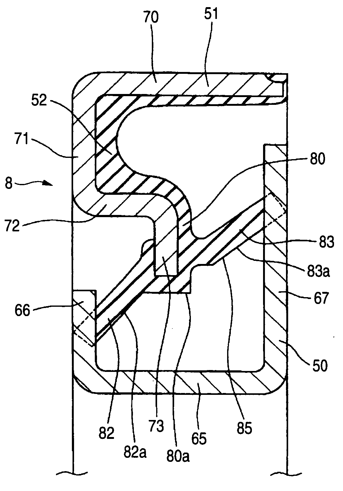
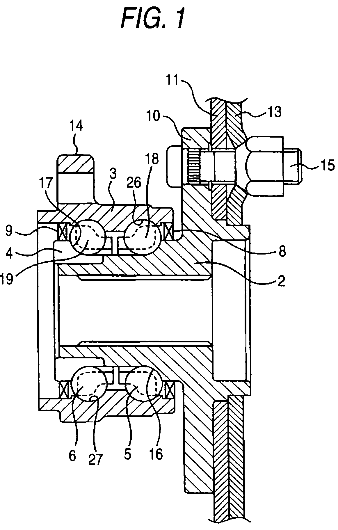
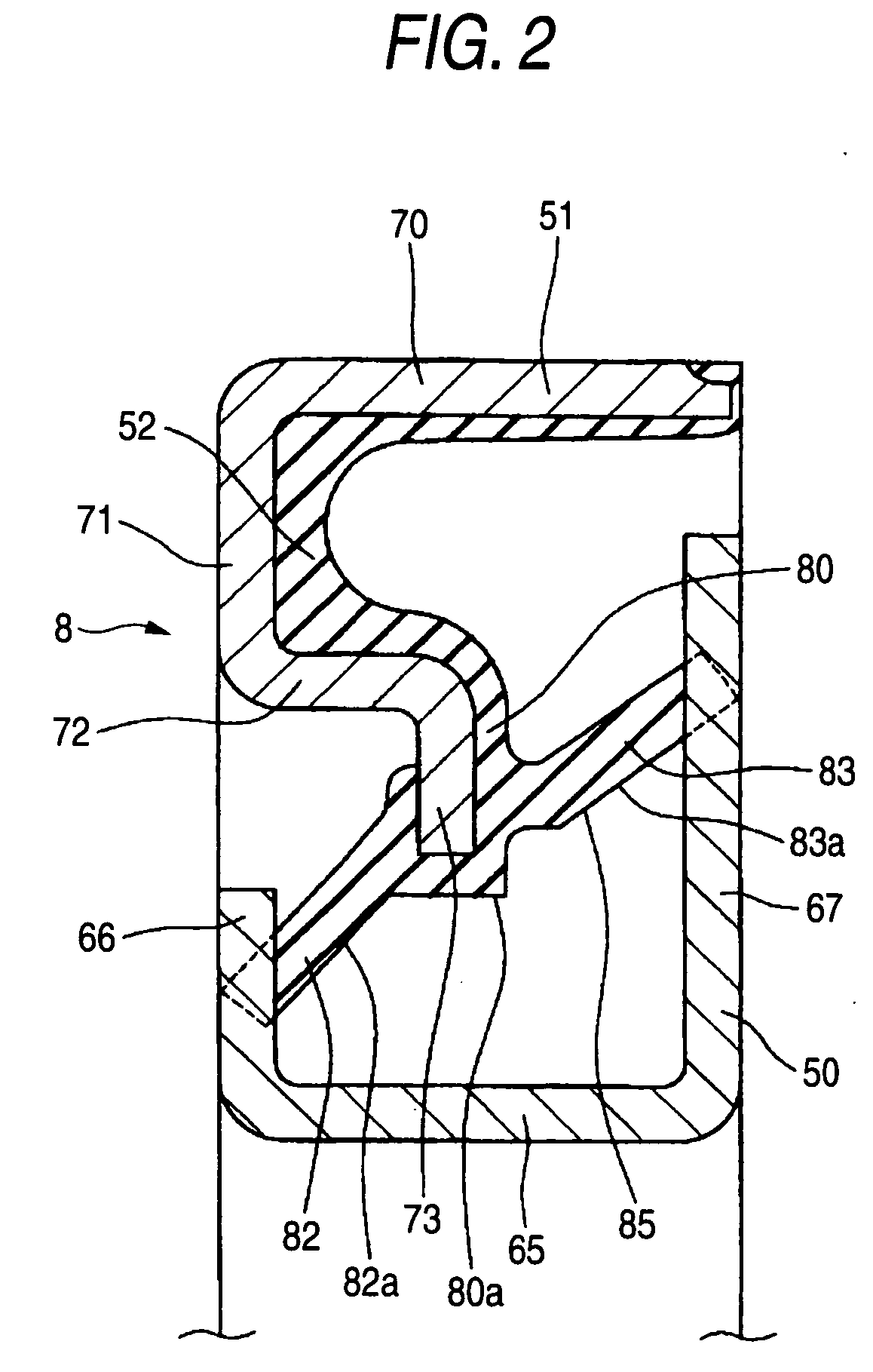
[0036]FIG. 1 is a cross-sectional view of a hub unit including sealing apparatuses 8 and 9 of the invention.

[0037]This hub unit comprises an inner shaft 2, an outer ring 3 serving as a second bearing ring, an inner ring 4, first balls 5, second balls 6, the first sealing apparatus 8 of the invention, and the second sealing apparatus 9 of the invention.

[0038]A brake disk mounting flange 10 of a disk-shape for the mounting of a brake disk 11 thereon is formed at one axial end portion of the inner shaft 2, and extends radially. A plurality of bolt passage holes are formed through the brake disk mounting flange 10, and are arranged in a circle generally concentric with this disk-shaped flange 10. The brake disk 11 is held against the brake disk mounting flange 10, and then a wheel member 13 is held against the brake disk 11, and in this condition the wheel member 13, together with the brake disk 11, is fixed to the brake disk mounting flange 10 by a plurality of bolts 15.

[0039]The inner...

second embodiment

[0067]FIG. 6 is a view similar to FIG. 2, but showing a sealing apparatus 208 of the invention.

[0068]In the sealing apparatus 208 of the second embodiment, those constituent portions similar to those of the sealing apparatus 8, 9 of the first embodiment will be designated by the identical reference numerals, respectively, and explanation thereof will be omitted. Furthermore, in the sealing apparatus 208 of the second embodiment, description of advantageous effects and modifications similar to those of the sealing apparatus 8, 9 of the first embodiment will be omitted.

[0069]In the sealing apparatus 208 of the second embodiment, a radially-inner distal end portion 263 of a core metal member 261 is shorter in radial dimension than that of the first embodiment. That portion (hereinafter referred to as “distal end base portion) 288 of a base portion 280 projecting radially toward a cylindrical portion 65 from the distal end of the core metal member 261 disposed close to the cylindrical p...


PUM


Abstract

A sealing apparatus includes a slinger which includes a cylindrical portion, and radially-extending portions and provided respectively at axially-opposite ends of the cylindrical portion and an elastic member which includes a base portion fixed to a surface of an inner radially-extending portion of a radially-extending core metal member, and a lip portion connected with the base portion. The lip portion is formed by a first axial lip contacting one radially-extending portion of the slinger and a second axial lip contacting the other radially-extending portion of the slinger. The elastic member is formed such that in an axial cross-section, the distance between a cylindrical portion-opposing surface of the elastic member radially opposed to the cylindrical portion and the cylindrical portion is increasing generally uniformly axially outward.

Description

BACKGROUND OF THE INVENTION[0001]This invention relates to a sealing apparatus, and more particularly to a sealing apparatus suitably used in a hub unit, a water pump or a motor which serves as a rolling bearing, and a bearing apparatus having the same.[0002]One conventional sealing apparatus is described in JP-UM-A-64-55371.[0003]This sealing apparatus includes a slinger, a core metal portion, and an elastic member.[0004]The slinger has a generally cup-shape in an axial cross-section.[0005]In the above cross-section, the core metal portion bisecting the slinger generally perpendicularly, and extends in a radial direction.[0006]The elastic member includes a base portion, and four thrust lips. The base portion has a generally block-shape, and is fixed to the core metal portion in a manner to cover the periphery of the core metal portion. First two of the four thrust lips are spaced from each other in the radial direction, and extend axially from a portion (which is not a distal end) ...

Claims


Application Information

Patent Timeline
Patent Type & Authority Applications(United States)
IPC IPC(8): F16J15/00B60B27/02F16C33/74F16J15/3232
CPCF16C33/7883F16C19/186F16J15/3256F16C2326/02
Inventor YAMAMOTO, KAZUTOSHITABATA, MASAHIRO
Owner JTEKT CORP
Why Eureka
Try Eureka