Method And System For Lighting Control

a technology of lighting control and method, applied in the field of methods, can solve problems such as the inability to measure lighting effects

Active Publication Date: 2008-08-28
SIGNIFY HLDG BV
View PDF11 Cites 85 Cited by
  • Summary
  • Abstract
  • Description
  • Claims
  • Application Information

AI Technical Summary

Benefits of technology

[0006]In particular, it is an object of the invention to obtain data about a lighting effect at a specific location caused by the operation of different lighting units and to control said operation dependent on said data and on location data, such that the light effect can be controlled for properties of the light effect dependent on location and the light effect can be dragged while maintaining properties of the light effect.
[0007]The above object of the invention is achieved by a method as described in claim 1. The location data can be obtained in a variety of manners which are well known by a person skilled in this art. Using said location data and some command input from the user of the user control device, the main control device may track the user control device while obtaining data about a light effect it caused at said location. As a result, the main control device is able to learn about light effects it causes at any location covered by the lighting arrangements by any combination of control commands it supplies to the lighting arrangements. Then, the main control device will be able to track a movement of the user control device. In addition, the main control device will then be able to maintain a specific light effect it caused at any location of the user control device, when the user control device is moving or not. This is like dragging a cursor on a computer screen by using a mouse. The main control device may apply any combination of control commands it finds suitable to maintain the lighting effect. The user will not have to worry or even care about it and he may, for example, pay all his attention to create and to achieve a lighting scheme. The above object of the invention is also achieved by a lighting system as described in claim 7.

Problems solved by technology

With the prior art system it is not possible to measure lighting effects caused by different lighting units on an object and to change controlling of the lighting units dependent on the measured lighting effects.

Method used


Image

  • Method And System For Lighting Control
  • Method And System For Lighting Control
  • Method And System For Lighting Control

Examples


Embodiment Construction

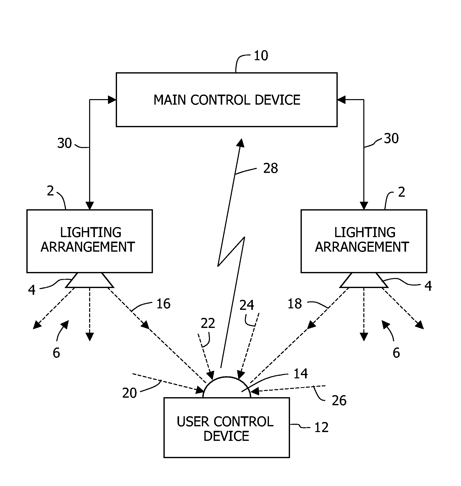
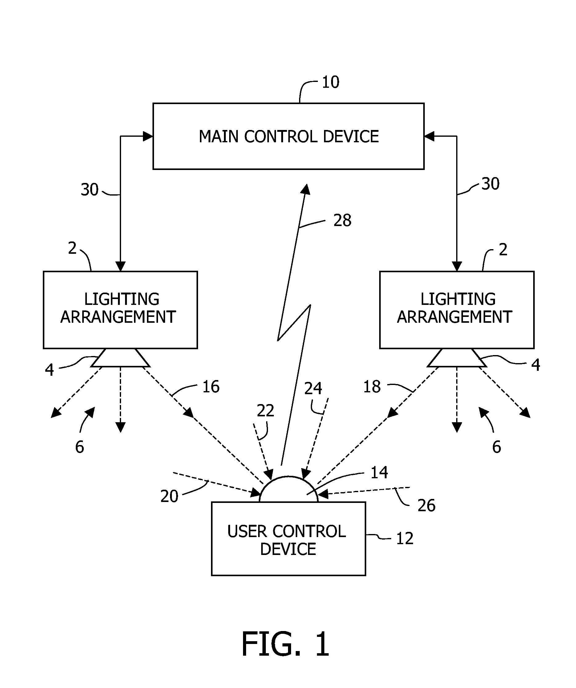
[0012]The system shown in FIG. 1 comprises one or more lighting arrangements 2, which may each comprise one or more lighting units, each lighting unit being schematically indicated by reference numeral 4. Lighting units 4 associated with a lighting arrangement 2 may be arranged at different locations in a room or in some other area to be lighted. Light emitted by a lighting unit 4 is indicated by a group of dashed arrows 6.

[0013]A lighting arrangement 2 comprises means, for storing an identification code, which is unique for the lighting arrangement 2, control means for supplying the lighting unit 4, and means for modulating the supply of a lighting unit 4 and therewith modulating the light output of the lighting unit 4, dependent on data, which at least comprises said identification code.

[0014]The system shown in FIG. 1 further comprises a main control device 10 and an user control device 12. In particular the user control device 12 is a hand held device, which is portable by a use...


PUM


Abstract

A method and a system for controlling at least one lighting arrangement (2), in which the lighting arrangement modulates the light (6, 16, 18) it emits by lighting arrangement data, which contains an identification code identifying the lighting arrangement, a user control device (12) is suitable to receive the light from the lighting arrangement and to derive therefrom the lighting arrangement data, the user control device measures a property of the received light, apart from it representing data, to provide additional data which is associated with the lighting arrangement which is associated with the identification code contained in the received data, the user control device transmits the lighting arrangement data and the additional data, and a main control device (10) is suitable to receive the data transmitted by the user control device and to therewith control the operation of the lighting arrangement.

Description

FIELD OF THE INVENTION[0001]The present invention relates in general to a method and device for controlling a lighting system comprising a plurality of light sources. The invention relates particularly to a method for controlling a lighting system and such a system as described in the preambles of claim 1 and 5 respectively.BACKGROUND OF THE INVENTION[0002]WO 2004 / 057927 discloses a method for configuration a wireless controlled lighting system. The prior art system comprises a central master control device, several local control master devices, which are linked to the central master device, and, associated with each local control master device, one or more lighting units and a portable remote control. Each lighting unit and the portable control are linked to their associated local control master device by a wireless connection. Light emitted by a lighting unit is modulated by an identification code, which was stored in the lighting unit before controlling the lighting unit. The por...

Claims


Application Information

Patent Timeline
Patent Type & Authority Applications(United States)
IPC IPC(8): H05B37/02G01J1/44
CPCH05B37/029H05B37/0272H05B47/19H05B47/155
Inventor FRUMAU, CONSTANTINUS CAROLUS FRANCISCUSVERBRUGH, STEFAN MARCUSNIJDAM, SANDERSIMPELAAR, BENNIE
Owner SIGNIFY HLDG BV
Why Eureka
Try Eureka