Clip-on video camera system for medical, surgical and dental applications

a video camera and clip-on technology, applied in the field of headmounted optical devices, can solve the problems of bulky wire frame configuration and awkward use of loupe mountings

Inactive Publication Date: 2008-08-28
GEN SCI
View PDF13 Cites 24 Cited by
  • Summary
  • Abstract
  • Description
  • Claims
  • Application Information

AI Technical Summary

Benefits of technology

[0006]The preferred embodiment further includes a first pivot arm coupled to the mount to which a video camera may be attached. The pivoting allows the camera to be rotated up and down relative to th...

Problems solved by technology

Although light sources and camera devices may be accommodated, and although they are independentl...

Method used


Image

  • Clip-on video camera system for medical, surgical and dental applications
  • Clip-on video camera system for medical, surgical and dental applications
  • Clip-on video camera system for medical, surgical and dental applications

Examples


Embodiment Construction

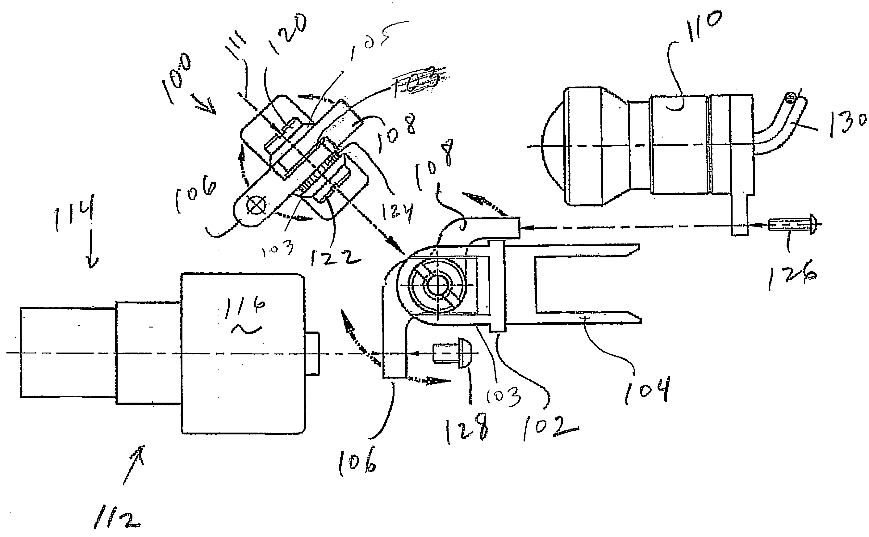
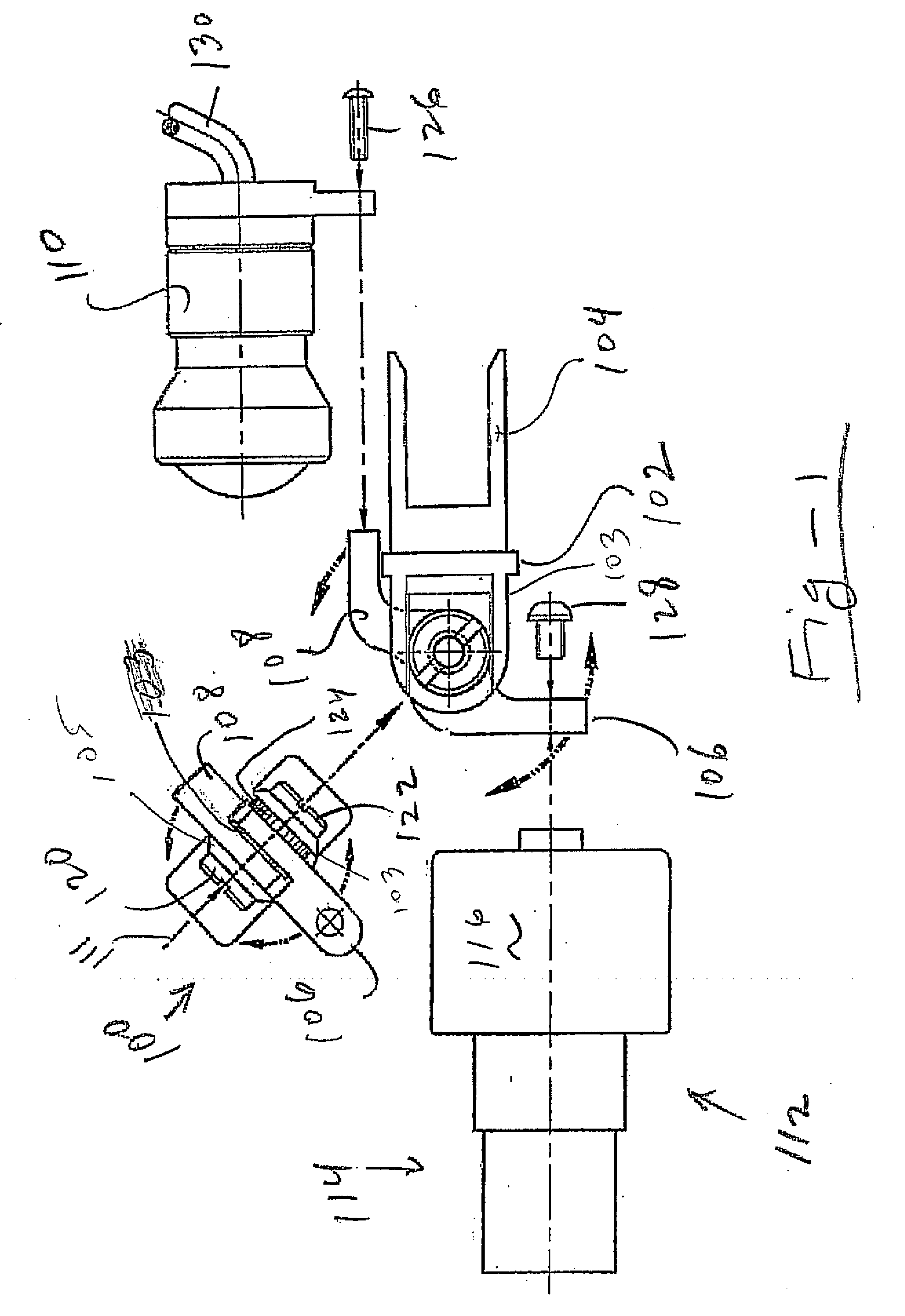
[0015]The preferred embodiment of the invention is depicted in FIG. 1. The system includes a mount 102 coupled to a clip structure 104 that may be used to clip onto loupes, headbands or frames. The mount 102 includes pair of opposing parallel plates 103, 105 that capture one or two pivot arms 106, 108. Although two pivot arms are shown, one for a camera (106) and another for a light source (108), the light source arm may be eliminated in place of a single arm providing a pivoting mount for the camera without a light.

[0016]If provided, the light source 110 is attached to pivot arm 108 using fastener 126, while the video camera, shown generally at 112, is attached with fastener 128. The light source includes a cable 130 bring electricity to an LED or incandescent bulb within housing 110, or the cable 130 may be an optical fiber bring light from a remote source. The video camera 112 includes an electronic unit 116 and imaging lens 114 with optional zoom. The cable from the camera unit ...


PUM


Abstract

A video camera system includes a mount with a clip-on structure adapted for attachment to a pair of eyeglass frames, loupes, or a headband. The preferred embodiment includes a camera mounted on a first pivot arm, and a light source mounted on a second pivot arm. One or both of the pivot arms are rotatable, enabling the beam from the light source and field of view of the camera to be aligned for a given working distance. Polarizing filters may be mounted to the camera, light source, or both to control glare, reflection or other undesired visual artifacts.

Description

REFERENCE TO RELATED APPLICATION[0001]This application is a continuation-in-part of U.S. patent application Ser. No. 11 / 678,637, filed Feb. 26, 2007, the entire content of which is incorporated herein by reference.FIELD OF THE INVENTION[0002]This invention relates generally to head-mounted optical devices of the kind used in medical, dental and surgical procedures and, more particularly, to a clip-on camera system that may be used with an aligned light source and mounted to eyeglass frames, loupes, or a headband.BACKGROUND OF THE INVENTION[0003]Clip-on optical accessories are known in the art. As one example, commonly assigned U.S. Pat. No. 6,493,136 discloses an optical accessory of the type used by medical professionals with a clip-on mount, enabling the entire assembly to be used with ordinary eyeglass frames. In an alternative embodiment, the assembly may be used with specialized frames, in which case the clip-on mount may be removed for a more permanent mounting of the assembly...

Claims


Application Information

Patent Timeline
IPC IPC(8): H04N5/225
CPCA61B19/26A61B19/5202H04N5/2251A61B2019/262A61B19/5212A61B2090/502A61B90/30A61B90/361A61B90/50A61B90/35G02B27/00G02B7/002G02B7/006G02B5/30G02B5/20H04N23/00
Inventor CHANG, BYUNG JIN
Owner GEN SCI
Why Eureka
Try Eureka