Touch panel

a touch panel and touch technology, applied in non-linear optics, instruments, optics, etc., can solve the problems of mechanical distortion warpage or distortion, humidity can be a factor of deteriorating polarizing characteristics, etc., to reduce the production cost of the touch panel, increase visibility, and reduce the effect of parts coun

Inactive Publication Date: 2008-08-28
PANASONIC CORP
View PDF4 Cites 13 Cited by
  • Summary
  • Abstract
  • Description
  • Claims
  • Application Information

AI Technical Summary

Benefits of technology

[0016]The present invention addresses the problems above. It is therefore the object of the present invention to provide a touch panel with good visibility capable of protecting a polarizing plate from distortion and deterioration,
[0018]Employing such a high-heat-resistant material for the phase-difference layer protects the polarizing plate from distortion and deterioration, increasing visibility and decreasing parts count and accordingly the production cost of a touch panel.
[0019]That is, the present invention offers a cost-reduced touch panel with good visibility.

Problems solved by technology

90° C. When the structure is subjected to great heat, for example, in full sunlight, warpage or distortion can occur.
Besides, humidity can be a factor of deteriorating polarizing characteristics.
The aforementioned inconveniencies can cause mechanical distortion of the touch panel and deteriorate optical characteristics, resulting in poor visibility of LCD element 10 disposed on the back surface of the touch panel.

Method used


Image

  • Touch panel
  • Touch panel
  • Touch panel

Examples


Embodiment Construction

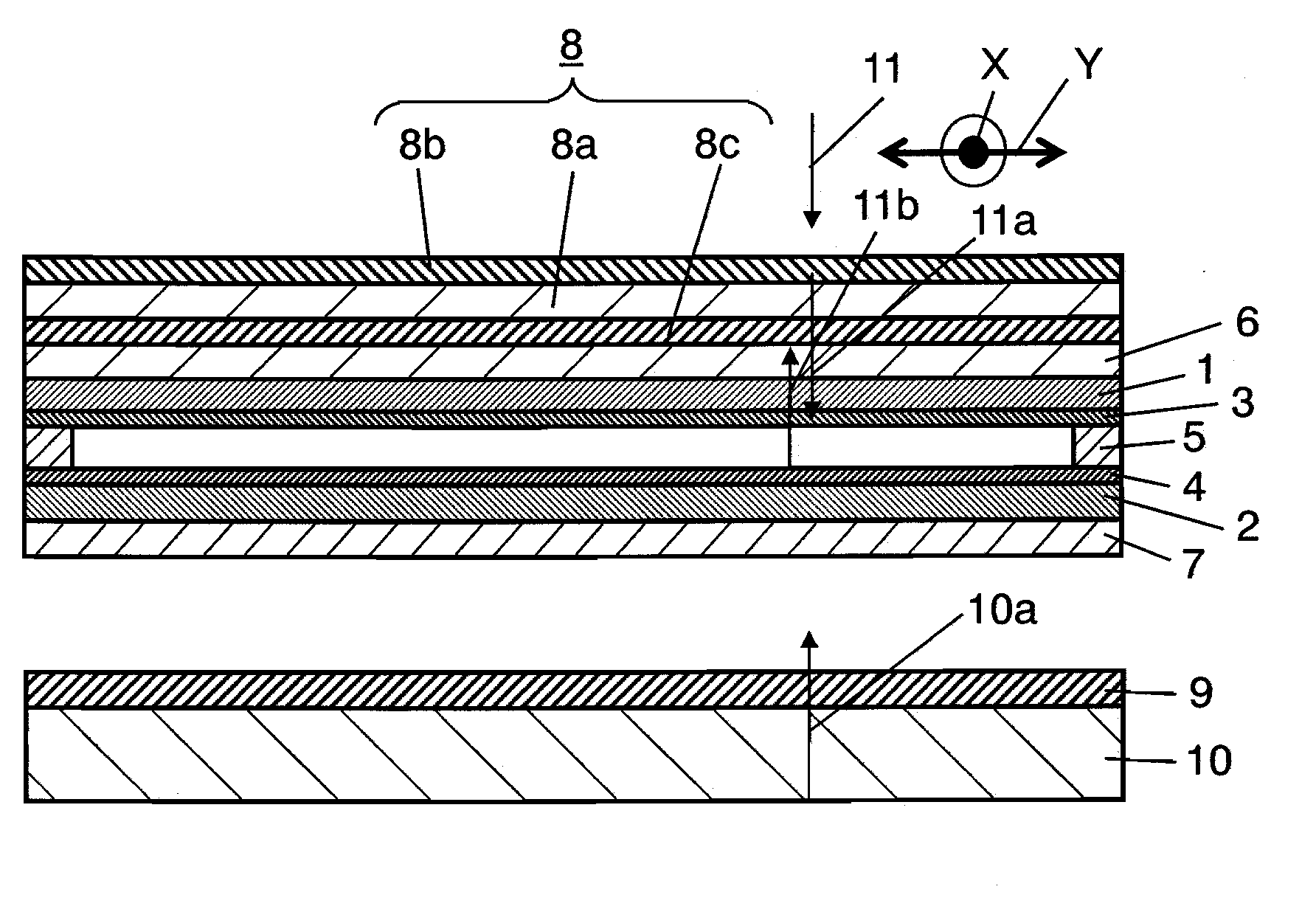
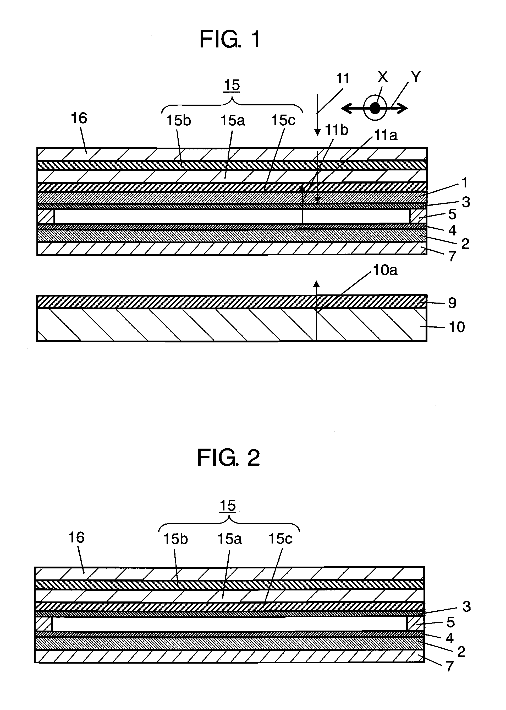
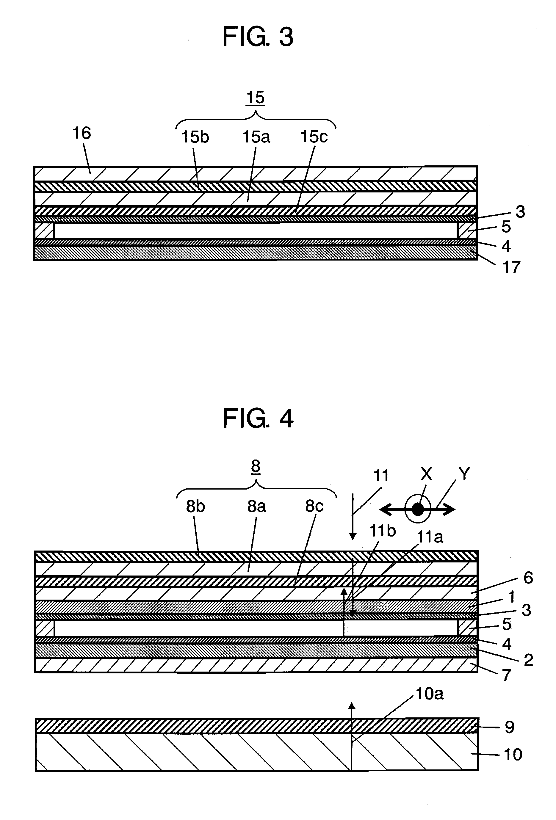
[0040]Hereinafter will be described the structure of an exemplary embodiment of the present invention with reference to FIGS. 1 through 3. For easy understanding of the structure, each figure shows dimensions enlarged in the thickness direction. Through the figures, like parts have similar reference marks and the description thereof will be omitted. Besides, as for the structure similar to that described in Background Art, similar reference marks are utilized and detailed description thereof will be omitted.

Exemplary Embodiment

[0041]FIG. 1 is a sectional view of a touch panel of an exemplary embodiment of the present invention. The touch panel of FIG. 1 has light-transmissive upper substrate 1, light-transmissive lower substrate 2 and polarizing plate 15. Upper substrate 1 is formed into a film made of polyethersulfone, polycarbonate or the like. Lower substrate 2 is made of glass, acrylic resin, polycarbonate or the like. Upper conductive layer 3 is formed on the bottom surface of ...


PUM

PropertyMeasurementUnit
heat resistanceaaaaaaaaaa
temperaturesaaaaaaaaaa
temperatureaaaaaaaaaa

Abstract

Disclosed here is a touch panel with improved visibility. Polarizing plate (15) of the touch panel has a laminated structure in which polarizing layer (15a) is sandwiched between upper protective layer (15b) and lower protective layer (15c). Of the three layers, lower protective layer (15c) is formed as a phase-difference layer with ¼ wavelength made of a cycloolefin-based polymer. The structure protects polarizing plate (15) from distortion and deterioration, offering good visibility. At the same time, the structure above contributes to reduced parts count and accordingly cost-reduced touch panel.

Description

TECHNICAL FIELD[0001]The present invention relates a touch panel mainly used for operations of electronic devices.BACKGROUND ART[0002]In recent years, there has been a growing trend to incorporate advanced various functions into electronic devices, such as mobile phones and car navigation systems. In such a trend, a touch panel has been widely employed for ease of operation. For example, a light-transmissive touch panel is attached on the front surface of a liquid crystal display (LCD) element. A user presses a touch panel with a finger or stylus, while viewing letters, symbols and graphics shown by the LCD element on the back surface of the touch panel and selects a desired function. As the demand for a touch panel increases, manufacturers have sought a user-friendly touch panel with good visibility.[0003]A conventional touch panel will be described with reference to FIG. 4.[0004]FIG. 4 is a sectional view of a conventional touch panel. For sake of clarity, the figure shows dimensi...

Claims


Application Information

Patent Timeline
Patent Type & Authority Applications(United States)
IPC IPC(8): G02F1/1333
CPCG02F1/13338G02F2201/50G02F1/133528
Inventor MATSUMOTO, KENICHITANABE, KOJI
Owner PANASONIC CORP
Why Eureka
Try Eureka