Arc fault circuit interrupter and method of parallel and series arc fault detection
a fault circuit and arc fault technology, applied in the field of circuit interrupters, can solve the problems of poor electrical connection, small reduction of load current, and inability to overload the capability of a conventional circuit breaker
- Summary
- Abstract
- Description
- Claims
- Application Information
AI Technical Summary
Benefits of technology
Problems solved by technology
Method used
Image
Examples
example 1
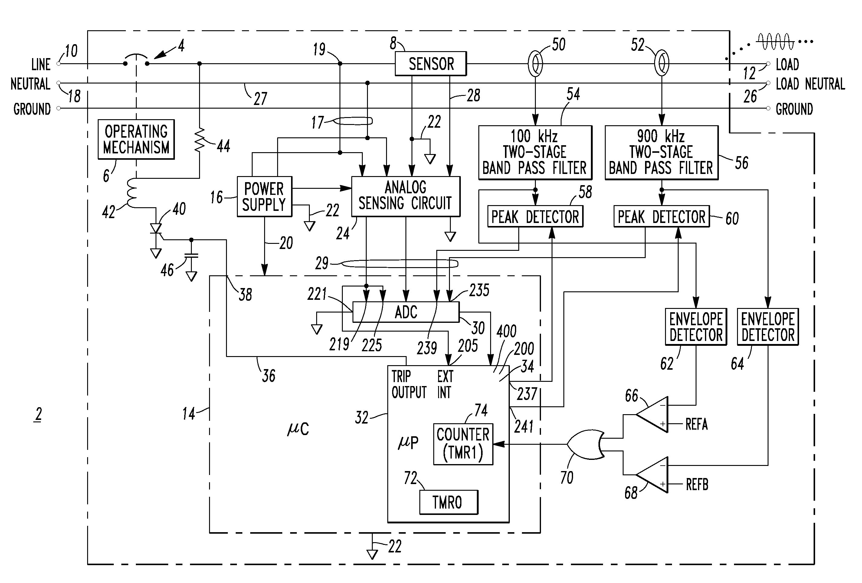
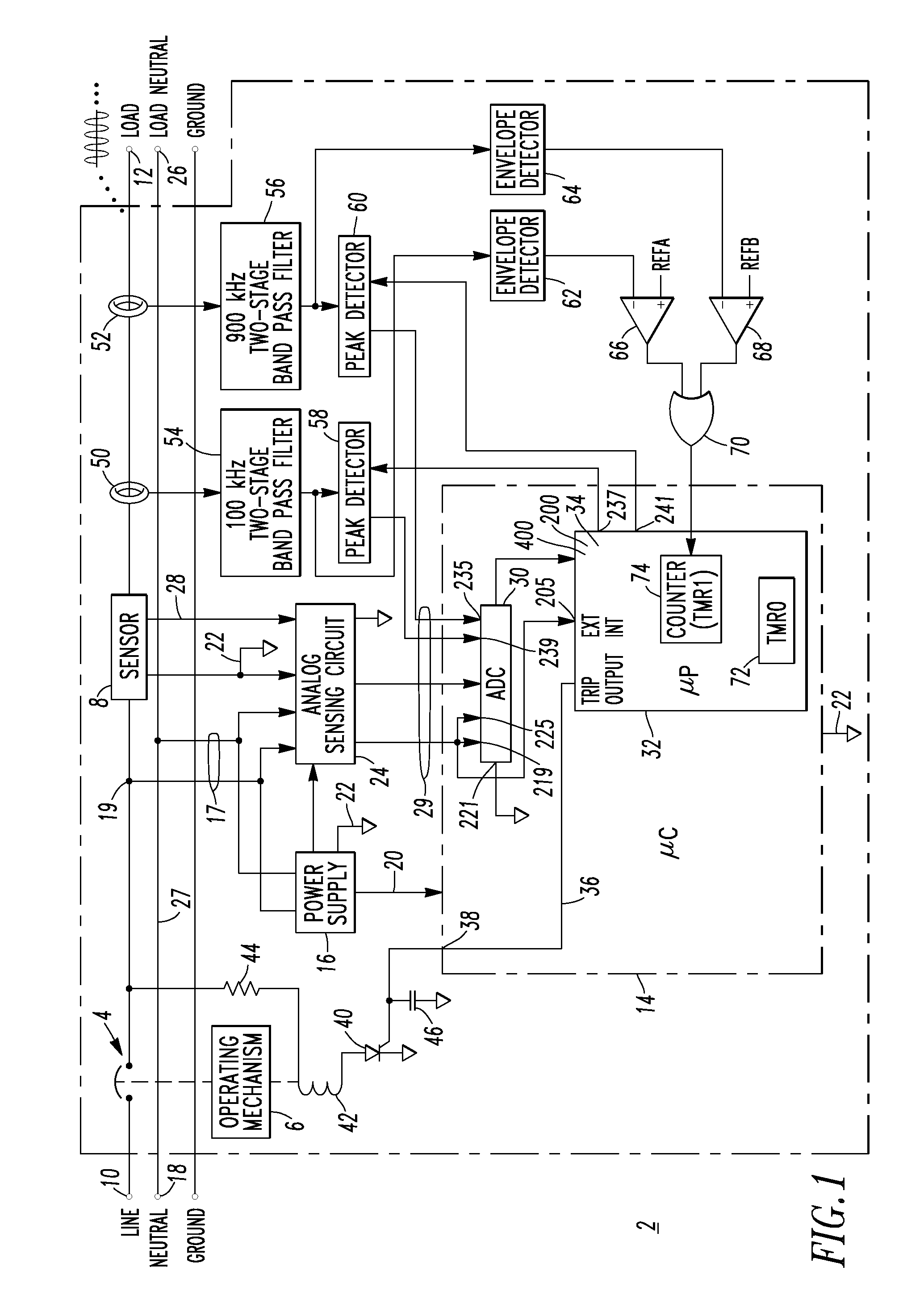
[0044]The disclosed parallel arc fault detection routine 34 ignores any line current pulses with a peak amplitude less than a predetermined amount (e.g., without limitation, about 50 A peak). If four half-cycles of line current with non-unity power factor occur in succession, then arc fault detection is inhibited for a predetermined time (e.g., without limitation, about 0.3 seconds). For example, this can distinguish a motor (e.g., without limitation, chop saw; air compressor motor) start inrush current transient from a parallel arc fault. If at least three half-cycles of line current with a continuously decreasing peak amplitude occur in succession (or in successive line cycles of like polarity), then the routine 34 inhibits arc fault detection for a predetermined time (e.g., without limitation, about 0.3 seconds). For example, this can distinguish an incandescent dimmer inrush current from a parallel arc fault. Otherwise, if the previous three conditions are not met, then any half...
example 2
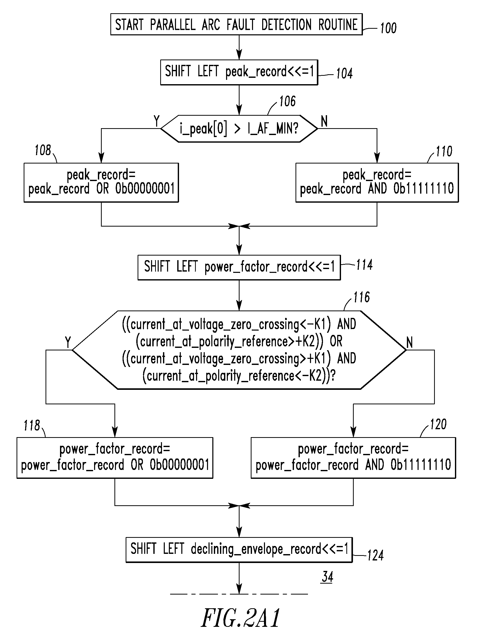
[0045]Referring to FIGS. 2A1-2A2 and 2B, the parallel arc fault detection routine 34 is shown. The routine 34 starts at 100 after which even steps 104-110 process peak current inhibition conditions and keep a record of whether recent AC line half-cycles have a peak current magnitude (i.e., absolute value) (i_peak) that is greater than a predetermined minimum arc fault peak current (I_AF_MIN) (e.g., without limitation, 50 A peak; any suitable current value which is considered to correspond to a potential parallel arc fault). At 104, the bits in peak_record are shifted left by one position. Then, at 106, it is determined if the most recent peak current magnitude (i.e., absolute value) (i_peak[0]) is greater than the predetermined minimum arc fault peak current. If so, then at 108, the lowest order bit in peak_record is set. Otherwise, at 110, the lowest order bit in peak_record is cleared.
[0046]After either 108 or 110, even steps 114-120 use AC (e.g., without limitation, 60 Hz) curren...
example 3
[0052]Step 126 of FIG. 2A2 is suitable regardless whether the sensor 8 of FIG. 1 is immune or susceptible to certain offset errors in sensing the peak line current (i_peak). For example, if the sensor 8 is a resistive current sensor, then the circuit 24 and ADC 30 are relatively immune to offset errors. However, if the sensor 8 is a Rogowski coil or other di / dt current sensor and the circuit 24 provides an integrator, then the ADC 30 may be susceptible to offset errors. Step 126 determines if the most recent peak current (i_peak[0]) is sufficiently less than the peak line current of the previous half-cycle of the same polarity (i_peak[2]). Here, those two peak currents of the same polarity have the same offset of the same polarity. Hence, the offset is not a problem.
[0053]Alternatively, when the sensor 8, circuit 24 and ADC 30 are relatively immune to offset errors, step 126 may determine if the most recent peak current (i_peak[0]) is sufficiently less than the peak line current of ...
PUM
 Abstract
Description
Claims
Application Information
 - R&D
- Intellectual Property
- Life Sciences
- Materials
- Tech Scout
- Unparalleled Data Quality
- Higher Quality Content
- 60% Fewer Hallucinations
Browse by: Latest US Patents, China's latest patents, Technical Efficacy Thesaurus, Application Domain, Technology Topic, Popular Technical Reports.
© 2025 PatSnap. All rights reserved.Legal|Privacy policy|Modern Slavery Act Transparency Statement|Sitemap|About US| Contact US: help@patsnap.com


