
Apparatus For Sighting-In A Gun

a technology for sighting and guns, applied in the field of guns, can solve the problems of acquiring knowledge, speed and wind direction, and can vary significantly

Active Publication Date: 2008-09-04
BARTLE DAVID ERIC
View PDF12 Cites 17 Cited by
  • Summary
  • Abstract
  • Description
  • Claims
  • Application Information

AI Technical Summary

Benefits of technology

[0006]It is an objective of the present invention to provide apparatus which enables a shooter to perform sighting-in of a gun, particularly a gun to be used in ranges over predetermined distances from the rifle to the target of up to 1,000 metres, and even over more than 1,000 metres.
[0008]The support frame itself is mounted on a pair of base connection blocks (a front connection block and a back connection block) that are adapted to be clamped to a base. The base may be any heavy, stable structure of metal, wood or other rigid material (for example, a purpose-built concrete block). The important characteristic of the base is that has a high mass compared with the gun, and that it is not affected by the recoil that is experienced when the gun is fired.
[0011]With such front stock (or barrel) locating means and rear stock clamping means, when a gun that is being sighted-in is fired, the recoil effect of firing the gun causes the gun barrel to lift and the entire gun to be rotated (by an amount which is dependent on the strength of the recoil effect) about the axes of rotation of the rear stock clamping members. However, the lateral positions of the locating pads on the horizontal bar should not change during this rotation of the gun and, since neither rear stock clamping member moves laterally, after the recoil effect, the gun can be relocated in precisely the same position on the support frame that it had before the gun was fired.
[0016]c) front stock (or barrel) locating means mounted on said support frame at or near the front end thereof; said front stock (or barrel) locating means comprising a horizontal bar supported above, and extending in a direction transverse to the elogate direction of said support frame, and restraining means mounted on said bar to prevent sideways movement of said front stock (or barrel);
[0018]e) gun tilting means for raising or lowering the rear stock clamping members relative to the top of the support frame, thereby to lower or raise the front of the barrel of the gun relative to its rear stock (if a rifle) or its handle (if the gun is a pistol).

Problems solved by technology

Acquiring that knowledge has been a problem for many years.
In addition, the setting up of the device requires knowledge that is often not available, and the parameters selected (especially wind speed and wind direction) can vary significantly in a very short time.

Method used


Image

  • Apparatus For Sighting-In A Gun
  • Apparatus For Sighting-In A Gun
  • Apparatus For Sighting-In A Gun

Examples


Embodiment Construction

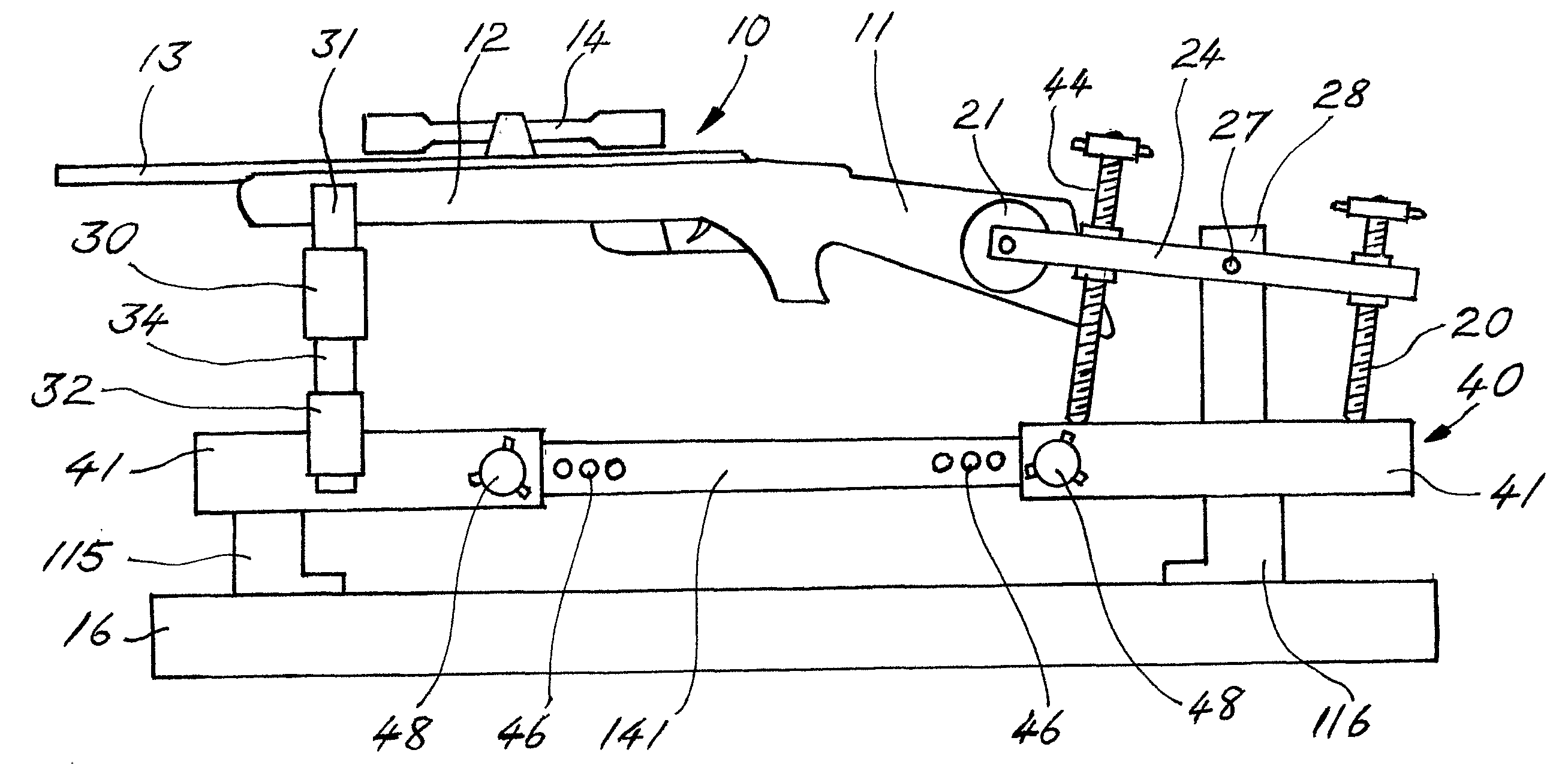
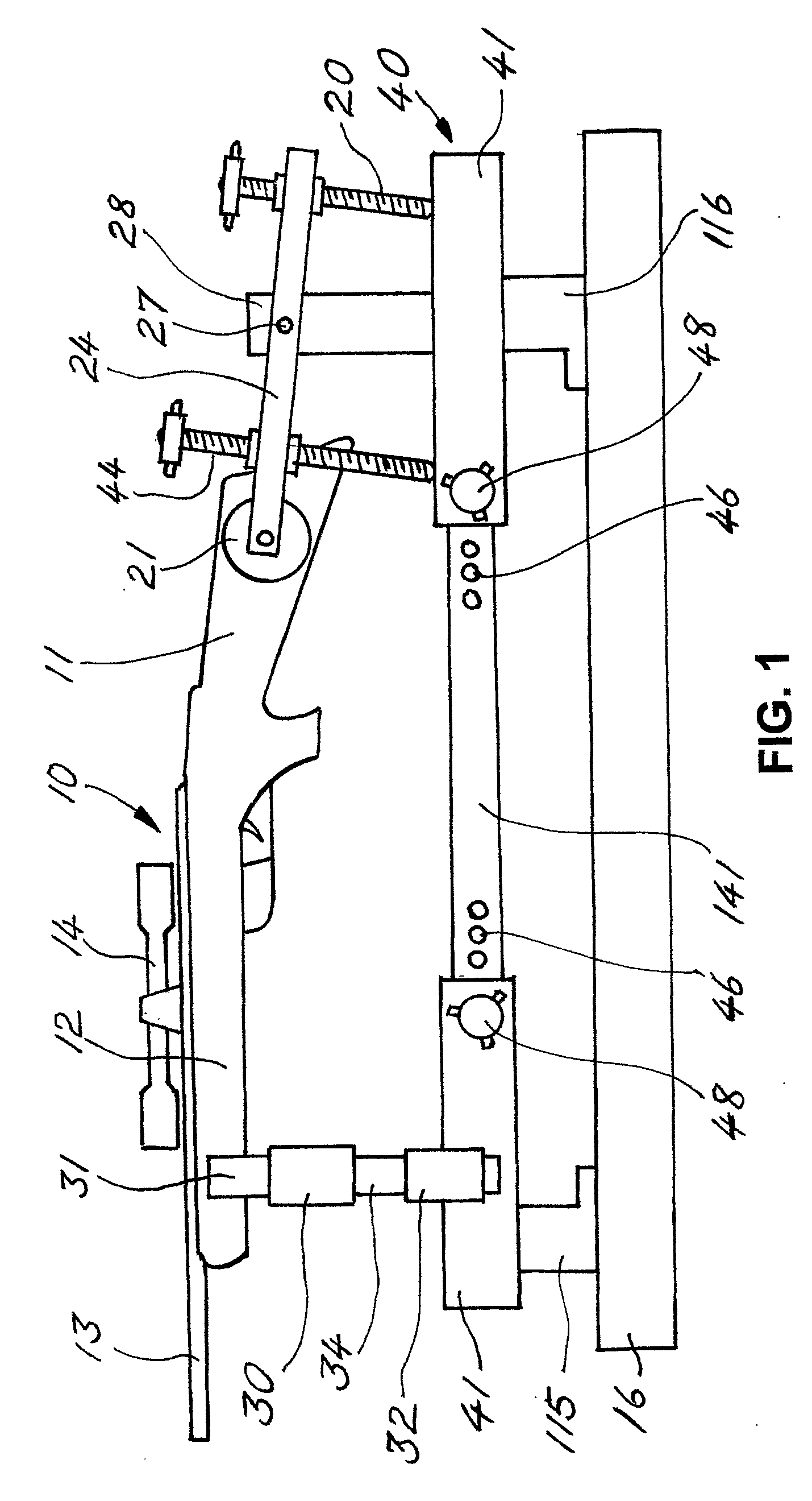
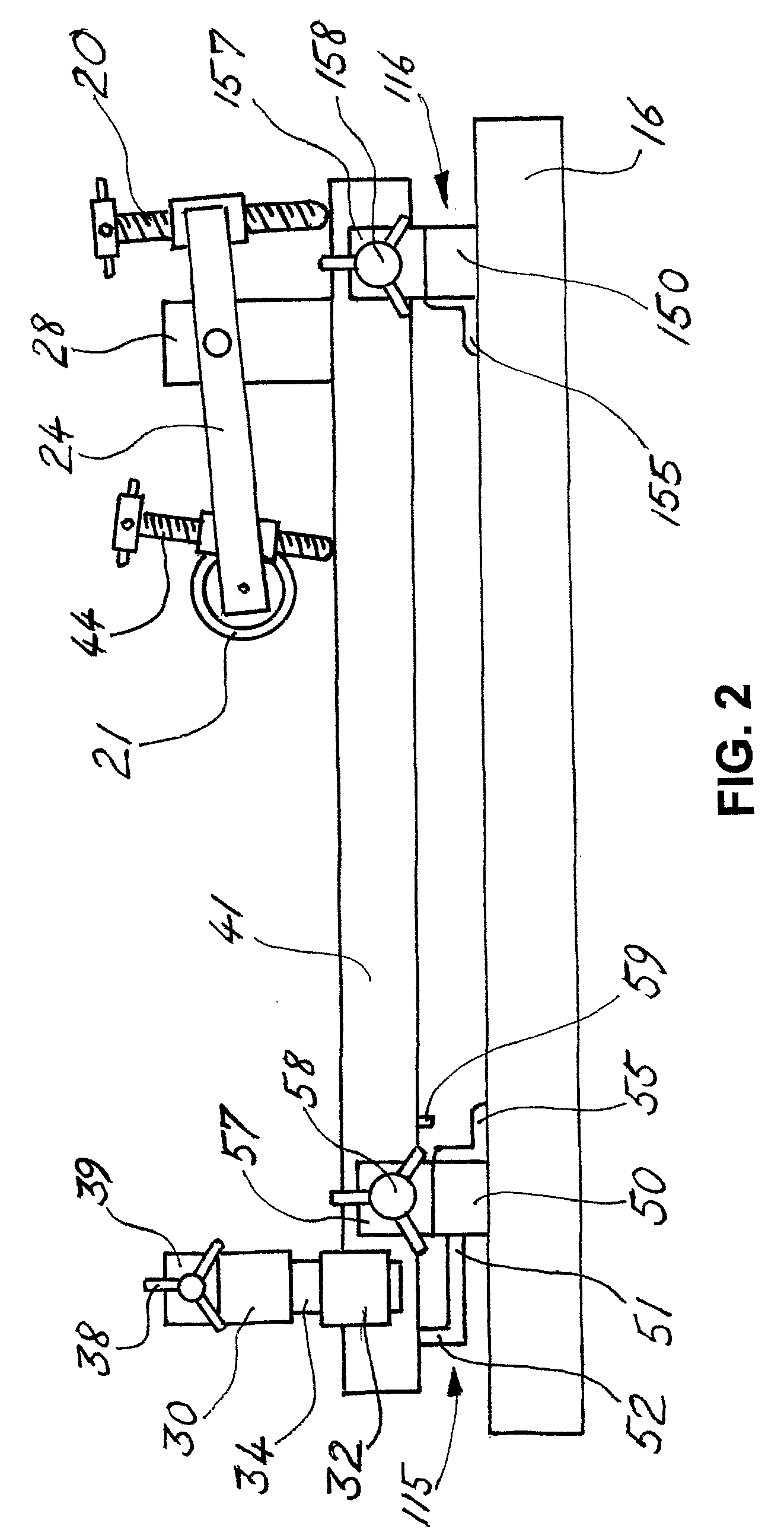
[0031]FIG. 1 shows a rifle 10 having a rear stock 11 which extends to a front stock 12. This rifle has a barrel 13. A telescopic sight 14 is mounted on the rifle 10. The rear stock (sometimes called the butt stock) 11 of the rifle 10 is held firmly by a pair of clamping members 21 of a stock clamping means mounted on a support frame 40. The front stock 12 (or the barrel 13) is located between a pair of pads 31 of a front stock (or barrel) locating means, which is also mounted on the support frame 40.

[0032]The support frame 40 is held firmly on a pair of mounting blocks 115 and 116 which are clamped to a base 16. Normally, the front mounting block 115 is the first mounting block to be clamped onto the base 16 and the rear mounting block 116 is then moved fore and aft until it is located in a required (or an appropriate) position, prior to its clamping onto the base 16.

[0033]In a prototype of the invention, constructed by the inventor, the support frame 40 comprises a pair of parallel...


PUM


Abstract

To sight-In a gun—especially a rifle (10)—it has to be held in the same position while it is fired at least twice, the gunsight (14) being adjusted after the first shot so that the gun sight shows the gun aimed at the point of impact of the first shot on the target. Apparatus to hold the gun while sighting-in is performed has a base (16) on which an elogate support frame (40) is mounted. The support frame (40) carries a rear stock clamping arrangement, with which clamping members (21) firmly hold the rear stock (11) of the gun. A gun barrel (13) or front stock (12) locating arrangement (30,31,32,34,37,39), also carried by the support frame, ensures that the front stock (or barrel) of the gun can be repositioned (if it has not been clamped) in the same position after a shot has been fired. Mounting blocks (115, 116) clamped to the base (16) include means to make fine adjustments of the lateral pointing of the gun. Course variation of the vertical pointing of the gun is effected by changing the height above the support frame (40) of a horizontal bar (30) of the front stock locating arrangement. Fine adjustment of the vertical pointing of the gun is effected by movement of pivot arms (24), on which the rear stock clamping members (21) are carried, about a pivot axis (27). Straps to prevent or limit gun movement due to recoil may be included.

Description

TECHNICAL FIELD[0001]This invention concerns guns. More particularly, it concerns the sighting-in of rifles and pistols (whether using rim fire or centre fire cartridges), shotguns, pneumatic rifles and other hand-held guns. The term “sighting-in of a gun” means the adjustment of the sighting system of the gun so that the accuracy with which any bullet, shell or quantity of shot, that has been fired from the gun, arrives at the intended target is optimised.BACKGROUND TO THE INVENTION[0002]On a rifle range or pistol range, knowledge of the accuracy of a rifle, shotgun or pistol is necessary if a shooter is to determine where to aim to hit a target (or to group shot on a target in the case of a shotgun). Acquiring that knowledge has been a problem for many years. All manufacturers of firearms perform some sighting-in of the guns they manufacture, but each owner of a gun has to work out, independently, how to aim the gun to have the best chance of success.[0003]In the specification of ...

Claims


Application Information

Patent Timeline
Patent Type & Authority Applications(United States)
IPC IPC(8): F41G1/54
CPCF41G1/54F41A23/16
Inventor BARTLE, DAVID ERIC
Owner BARTLE DAVID ERIC
Features
  • Generate Ideas
  • Intellectual Property
  • Life Sciences
  • Materials
  • Tech Scout
  • Unparalleled Data Quality
  • Higher Quality Content
  • 60% Fewer Hallucinations
Learn More