This known type of
system requires use of a tool such as a spanner to release the nuts and is thus
time consuming.
Although FR2782471 discloses a quick release wheel hub assembly it may be considered to be unnecessarily complicated in that the bearings are located in the forks rather than in the wheel hub assembly.
A problem with the
system disclosed in FR2782471 is that it is highly desirable to use commonly available wheels and wheel hub assemblies wherein the wheel hub itself comprises the bearings, U.S. Pat. No. 5,165,762 also discloses a form of quick release apparatus that comprises a hub having a spindle passing therethrough and to which there is attached a
cam lever at a first end and an end cap located at the other end.
However the rigidity of the wheel mounting and assembly is known to be less than optimal.
Although U.S. Pat. No. 6,386,643 provides improved rigidity, the fact that the dropouts are of the open bore type results in less than optimal rigidity as regards the securement of the wheel hub to the forks of the vehicle.
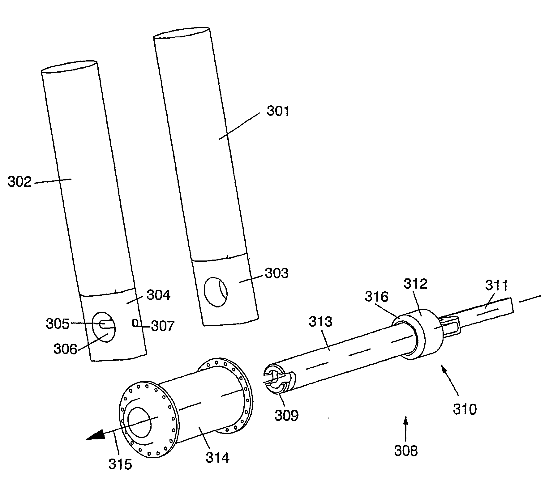
By fully closed bore it is meant a wheel mounting orifice that has a circumference of 360° at all times. However use of such fully closed bore dropouts means that the above mentioned quick release assemblies, as exemplified by U.S. Pat. No. 6,386,643, are not able to be inserted into the dropouts without substantially dismantling the axle assembly and thus losing the intended quick release effect of the quick release assembly.
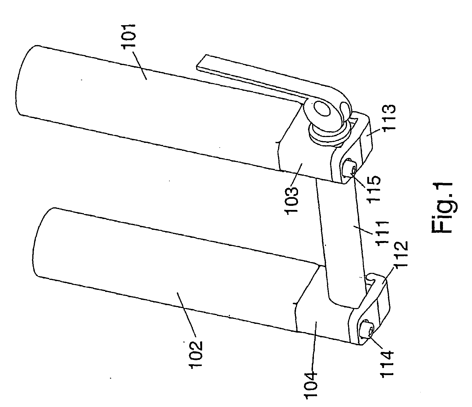
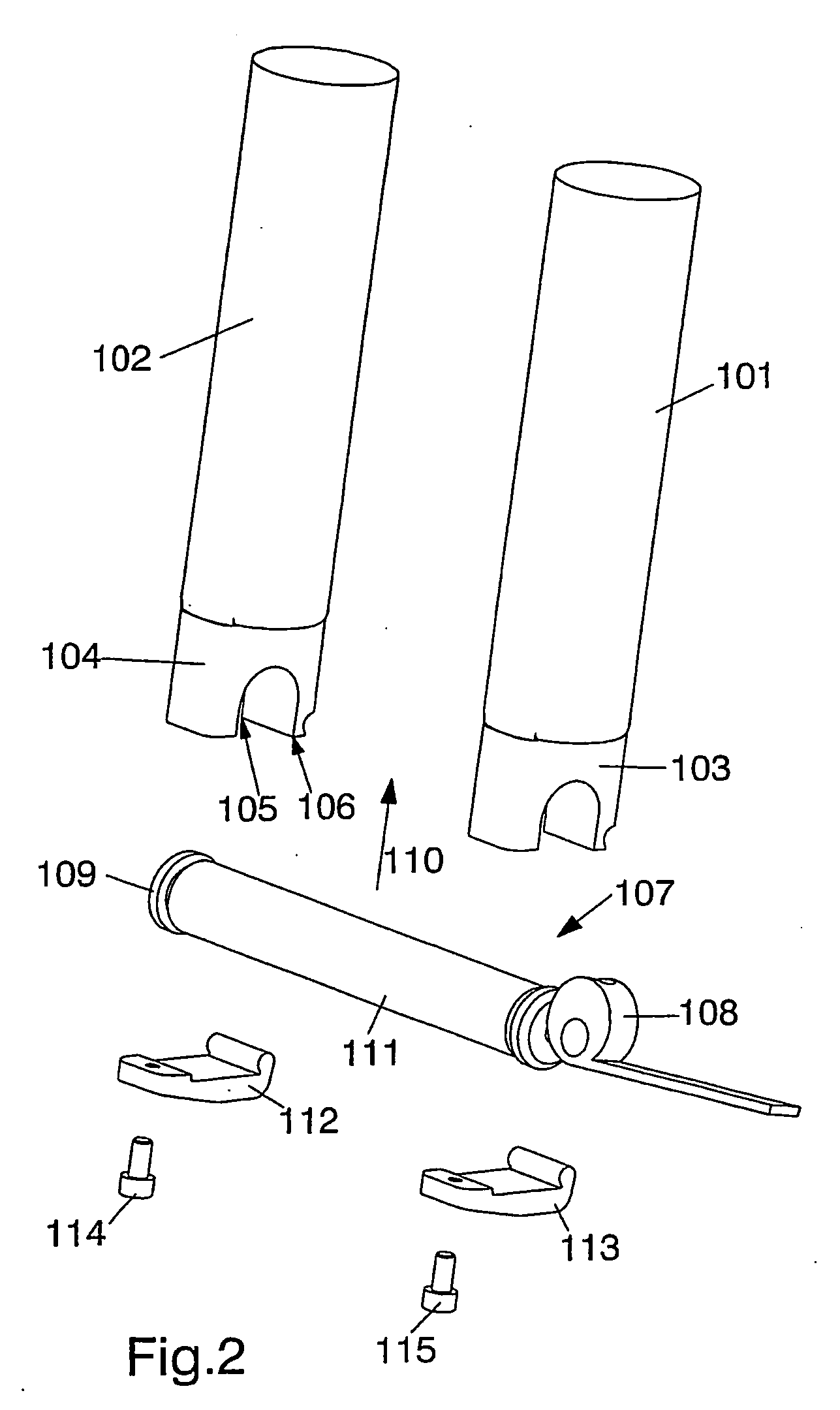
A problem with the fork / axle assembly schematically illustrated in FIGS. 1 and 2 is that it is difficult and
time consuming to remove and replace the axle from / to the open bore dropouts in view of the need to respectively remove and replace the plates.
A further problem is that frequently the bolts or plates may be lost or damaged during removal of a wheel or
insertion of a wheel into the fork dropouts.
Without disassembling the QR spindle
system for this type of fork / axle assembly (thereby removing the spindle) it is simply not possible to fit the QR axle in to the dropouts.
Although an open bore dropout QR system of the type discussed earlier could be dismantled and then fitted through a closed bore dropout system it would be
time consuming and there is the risk of loss of and / or damage to the separated components.
A problem associated with both of the aforementioned Rockshox systems is that, although the axle assembly is fixed to the dropouts, the rigidity of these systems is considered to be less than optimal.
Not only is an alternative required, but the systems designed by Rockshox are considered to be somewhat less than optimal in that the clamping effect of the quick release cams is configured to provide a force on the axle in the direction defined by a
radius extending between a point on the circumference of the axle and a point on the longitudinal axis located along the length of and at the centre of the axle.
In the sport of
mountain biking high forces (especially as regards front fork systems) may potentially cause the axle in these systems to move, particularly if the
cam or cams are not tightened sufficiently or if they become loosened in some way during operation of the bike.
Use of suspension forks can create unbalanced compressional and tensional forces in the fork legs during cornering and manoeuvering of the bicycle.
The known methods for securing larger
diameter axles, commonly 20 mm in
diameter, differ in design, but each suffers from either requiring specialist tools for the removal of the wheel and / or requires an excessive number of operations to be completed before the wheel can be removed by virtue of the axle being displaced longitudinally through closed-bore dropouts rather than simply being dropped out as is the case with open-bore dropouts.
