Energy Storage Unit

a technology of energy storage unit and storage element, which is applied in the direction of electric vehicles, electric vehicles, electrical equipment, etc., can solve the problems of premature failure of the entire energy storage unit, excessive charging of storage elements which are fully charged prematurely, and total discharge or even inverse charges of storage elements with a low capacity, so as to reduce the voltage threshold value, reduce the voltage, and reduce the effect of voltag

Active Publication Date: 2008-09-04
CONTI TEMIC MICROELECTRONIC GMBH
View PDF16 Cites 44 Cited by
  • Summary
  • Abstract
  • Description
  • Claims
  • Application Information

AI Technical Summary

Benefits of technology

[0006]The invention relates according to a first aspect to an energy storage unit with several storage elements which are switched in series, and to a charge redistribution circuit. The energy storage unit is installed in such a manner that the voltage of the storage elements is measured and is compared with a voltage threshold value. When the voltage threshold value is exceeded by a storage element, the charge redistribution circuit removes charge from this storage element, thus reducing its voltage. In addition, a storage-related temperature determination is conducted, and the voltage threshold value is set variably in dependence on the determined temperature in such a manner that as the temperature increases, the voltage threshold value is reduced.
[0007]A further aspect relates to an energy storage unit for a motor vehicle which is equipped with an electric drive or an electric hybrid drive, with several storage elements which are switched in series and a charge redistribution circuit. The energy storage unit is installed in such a manner that the voltage of the storage elements is measured and is

Problems solved by technology

With a simple series connection, differences of this nature can on the one hand, during discharging processes, lead to total discharges or even to inverse charges of storage elements with a low capacity, while on the other hand, during charging processes, lead to excess c

Method used


Image

  • Energy Storage Unit
  • Energy Storage Unit
  • Energy Storage Unit

Examples


Embodiment Construction

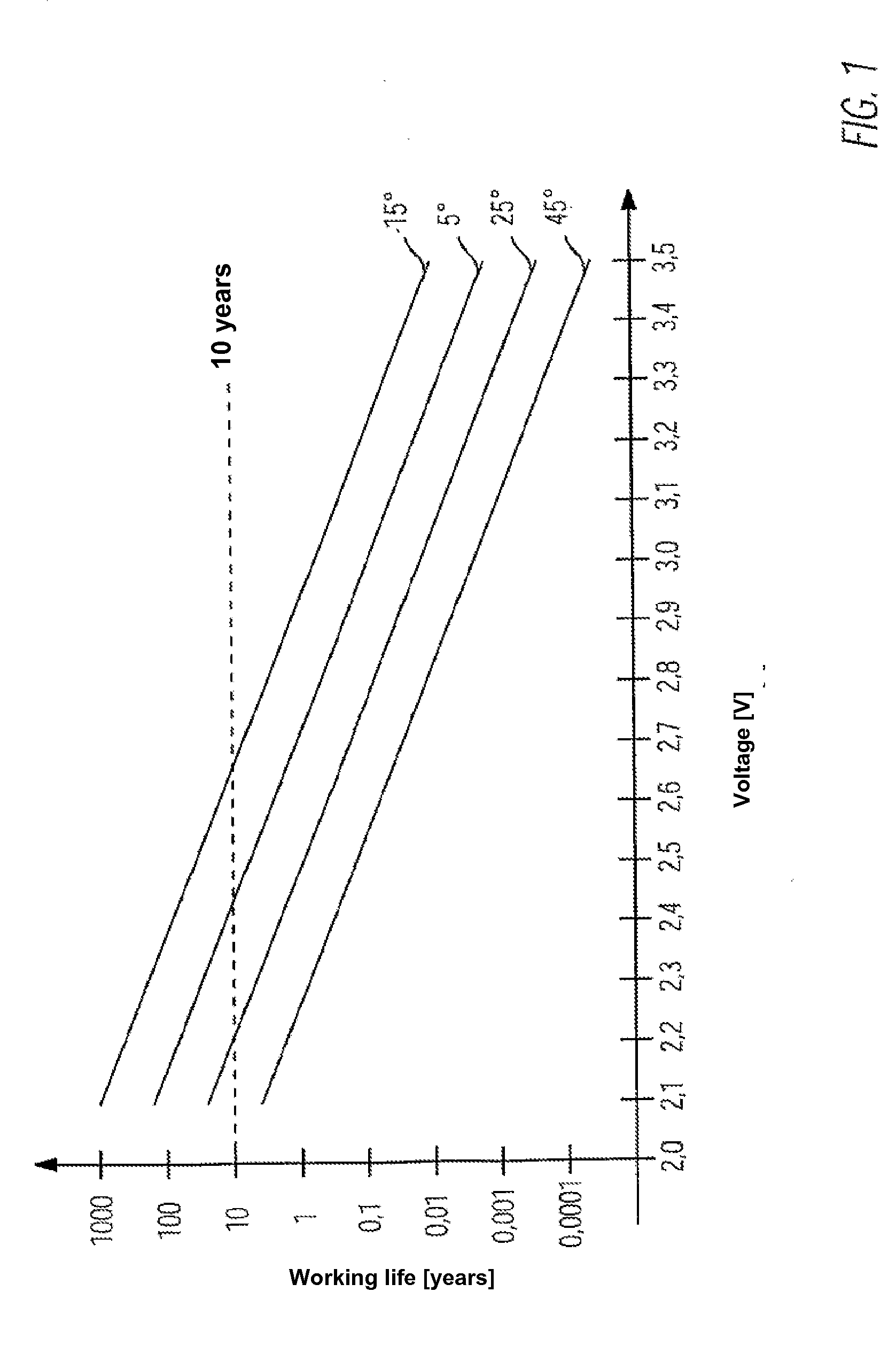
[0022]Before the working life voltage diagram of an exemplary double-layer capacitor as shown in FIG. 1 is explained, a few comments will be made with reference to the preferred embodiments.

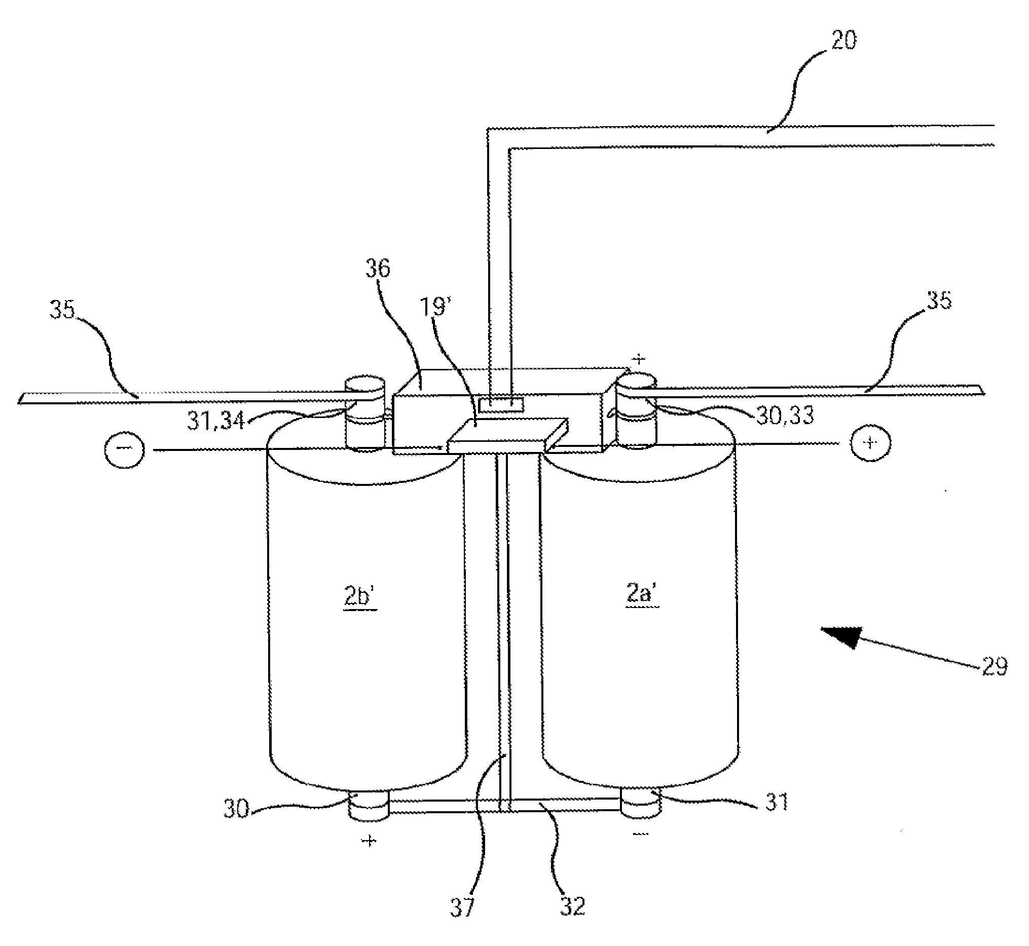
[0023]These relate to an energy storage unit with several storage elements which are switched in series, and which are galvanic cells, capacitors, double-layer capacitors etc. The reason for switching the storage elements in series is that, as has been explained in the introduction, the energy storage unit—when regarded as a whole—is required to deliver a far greater operating voltage than the nominal operating voltage of an individual storage element. For example, an energy storage unit with 20 2.4 V storage elements which are switched in series delivers a voltage of approx. 48 V. With certain embodiments, an individual storage element can be formed as a result of the parallel switching of several sub-elements; these are referred to as a “storage element” regardless of their inner structure.

[002...


PUM


Abstract

An energy storage unit has several storage elements (2, 2′) which are switched in series and a charge redistribution circuit (6, 6′). The latter is installed in such a manner that the voltage of the storage element (UELn, UEln′) is measured and compared with a voltage threshold value (UTHRn, UTHR, UTHRn′, UTHR′). When the threshold value is exceeded by a storage element, it removes charge from said storage element, thus reducing its voltage. According to one aspect, a storage-related temperature determination is conducted, and the threshold value is set variably in dependence on the determined temperature (Tn, T) in such a manner that it is reduced as the temperature increases. According to a further aspect, the threshold value is set variably in dependence on the current vehicle operating state, in such a manner that it is set higher for relatively brief periods of time when the storage or removal requirement is relatively high. According to an additional further aspect, the threshold value is set lower for storage elements with a relatively advanced age than for those with a less advanced age.

Description

FIELD OF THE INVENTION[0001]The invention relates in general to the storage of electrical energy, and for example to an energy storage unit with several storage elements which are switched in series and with a charge redistribution circuit. The energy storage unit is installed in such a manner that the voltage of the storage element is measured and is compared with a voltage threshold value, wherein, when a storage element exceeds the voltage threshold value, the charge redistribution circuit removes charge from said storage element, thus reducing its voltage.BACKGROUND OF THE INVENTION[0002]Storage units for electrical energy are usually constructed from individual storage elements. The nominal operating voltage of these storage elements is usually relatively low, e.g. in the range of between 2 and 2.5 V with double-layer capacitors. For most applications, however, a far higher operating voltage of the energy storage unit is required. For example, the electric drives of hybrid moto...

Claims


Application Information

Patent Timeline
IPC IPC(8): H02J15/00
CPCY02T10/7055H02J7/0016Y02T10/70
Inventor RUDORFF, AXELMALIK, MANFRED
Owner CONTI TEMIC MICROELECTRONIC GMBH
Why Eureka
Try Eureka