Capacitance sensor

a capacitive sensor and capacitance technology, applied in the field of capacitive sensors, can solve the problems of false detection of human body, inability of the sensor to detect a catch of a lower load or a catch earlier, and difficult to detect a catch by indirect detection system, etc., to achieve more accurate detection, improve resistance to extraneous noise, and improve the effect of resistan

Inactive Publication Date: 2008-09-04
ORMON CORP +1
View PDF4 Cites 61 Cited by
  • Summary
  • Abstract
  • Description
  • Claims
  • Application Information

AI Technical Summary

Benefits of technology

[0022]One or more embodiments of the present invention provide a construction in which the contact detecting electrode functions as a ground electrode. This construction eliminates the need for disposing a ground electrode separately. Further, this construction can improve resistance to extraneous noises and hence can perform a more accurate detection.
[0023]Further, one or more embodiments of the present invention provide a construction in which the detection electrodes and the shield electrode are held by a non-conductive material and are integrally constructed. In this case, the relative positions of the respec...

Problems solved by technology

Of these systems, the indirect detection system has disadvantages in that it is difficult for the indirect detection system to detect a catch as early or as reliably as the direct detection system or to detect a catch with as low a load.
A pressure-sensitive switch has been used as a sensor of this kind, so that it is impossible for the sensor to detect a catch of a lower load or to detect the catch earlier.
This presents a problem that, although a human body or the like is not actually caught, the sensor falsely detects the human body or the like as being caught.
However, with these technologies, near the positio...

Method used


Image

  • Capacitance sensor
  • Capacitance sensor
  • Capacitance sensor

Examples


Embodiment Construction

[0036]Hereinafter, the embodiments of the present invention will be described with reference to the drawings.

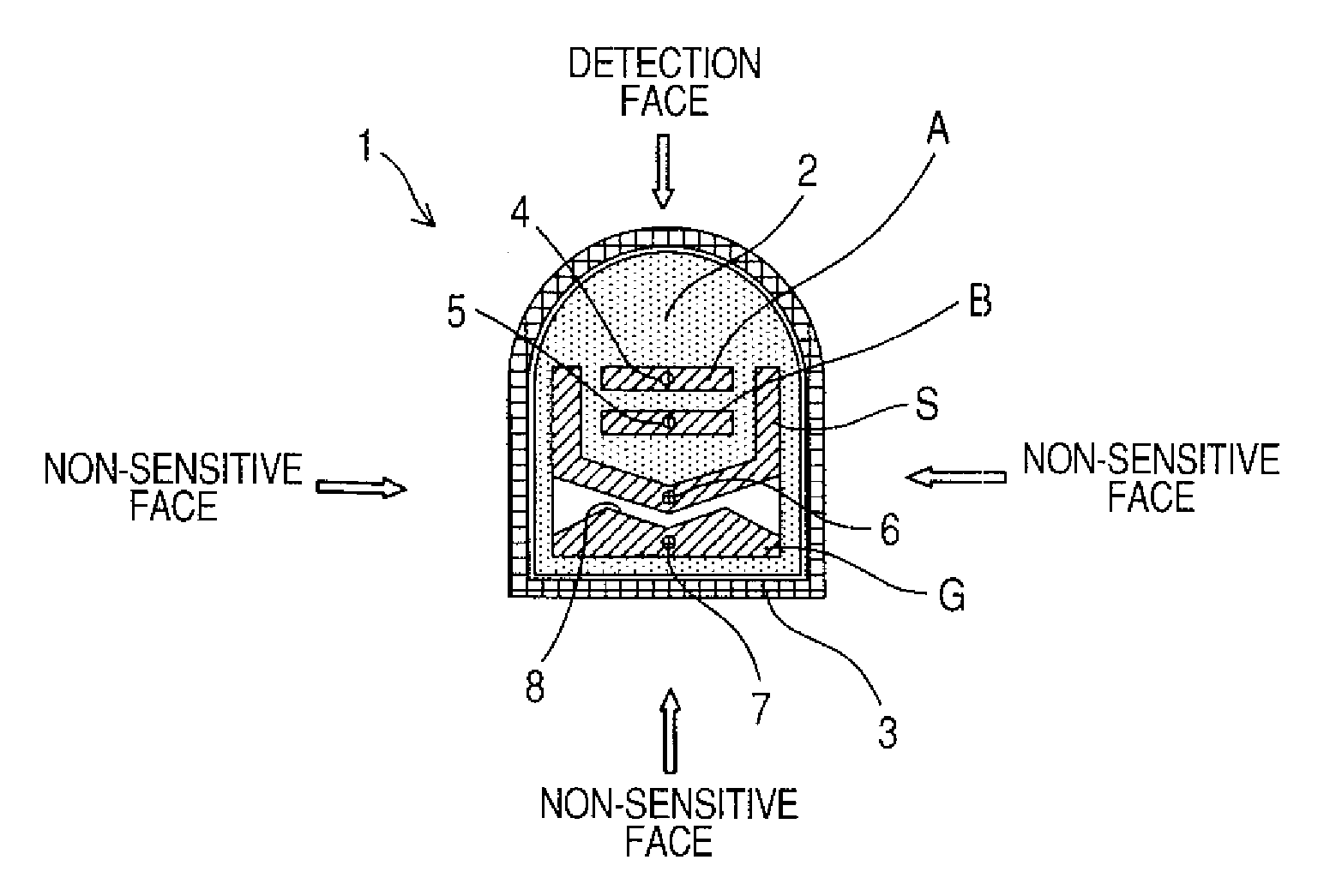
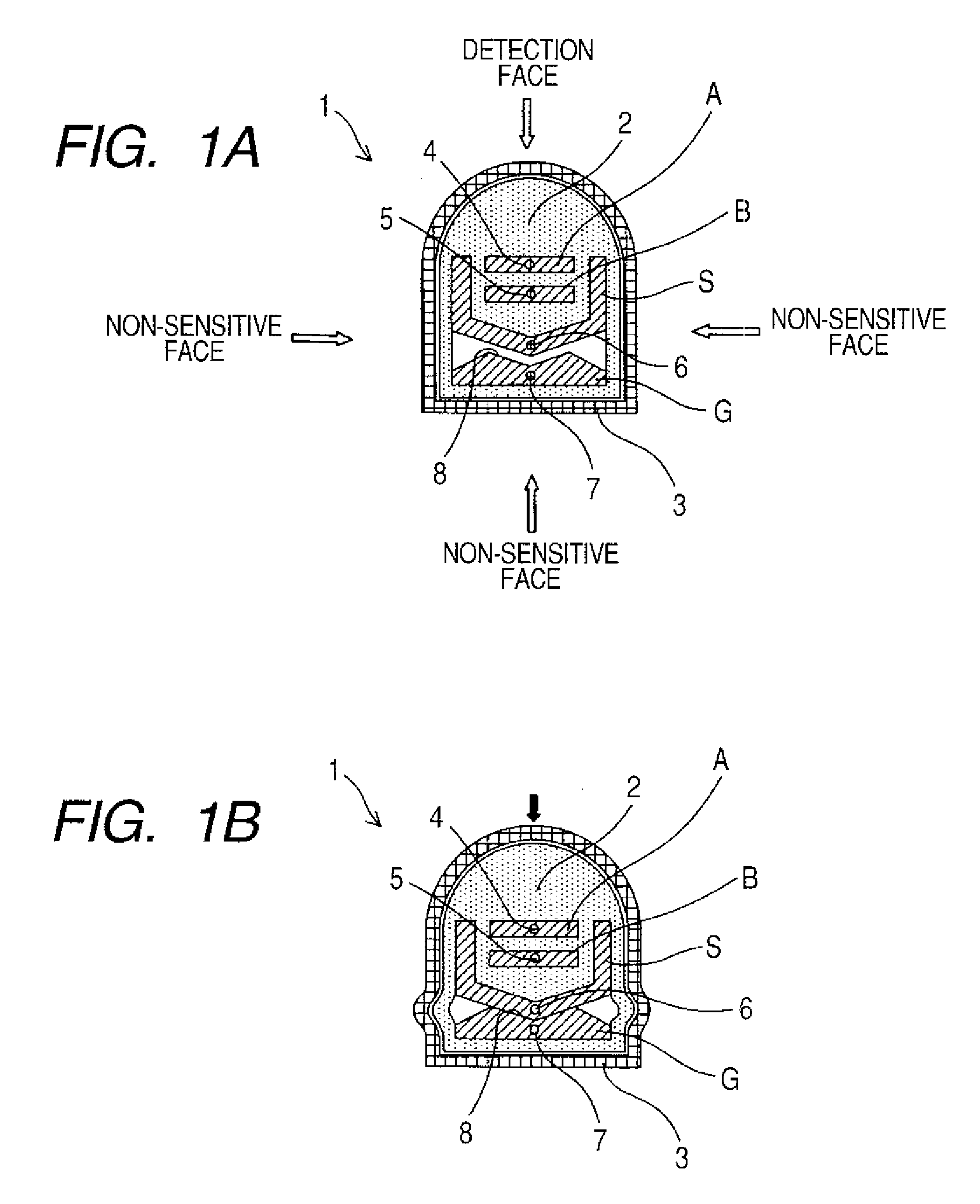
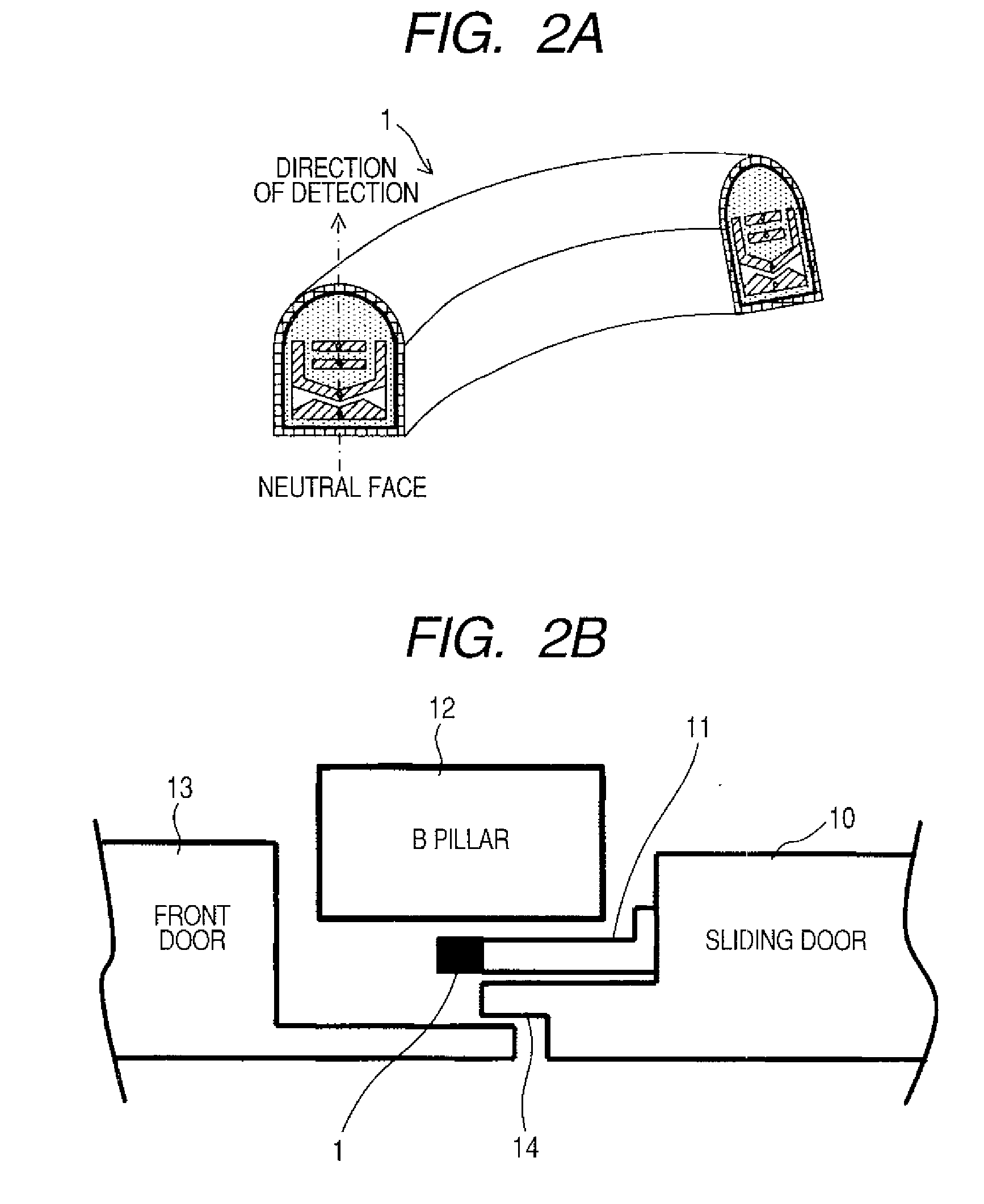
[0037]FIG. 1A is an illustration showing the internal construction of a sensor body 1 of a capacitance sensor, and FIG. 1B is an illustration showing an operating state as a touch sensor of the sensor body 1 (state in which the sensor is displaced by an object to be detected). Further, FIG. 2A is a perspective view showing the entire sensor body 1, and FIG. 2B is a horizontal sectional view showing the sensor body 1 placed on an automobile and its peripheral construction. FIG. 3 is an illustration showing the internal construction and the mounting structure of the sensor body 1. Still further, FIG. 4 is a perspective view showing an example in which the sensor body 1 is mounted on an automobile. Still further, FIG. 5 is a block diagram schematically showing a catch detecting device including a capacitance sensor according to one or more embodiments of the present invention (i...


PUM


Abstract

A code-type sensor for detecting a change in capacitance includes a plurality of detection electrodes for detecting a change in capacitance, a shield electrode surrounding the plurality of detection electrodes so as to restrict a detection range of the capacitance and having an opening in a direction of detection, and a contact detecting electrode for detecting contact disposed along a longitudinal direction of the sensor. The detection electrodes are disposed at a position close to the opening in the shield electrode and at a position far from the opening in the shield electrode. The contact detecting electrode is disposed on a back side in the direction of detection of the shield electrode. The respective detection electrodes are integrally connected to each other in such a way as to be held in a separate state, the detection electrodes and the shield electrode are integrally connected to each other in such a way as to be held in a separate state, and the shield electrode and the contact detecting electrode are kept in such a way as to be held in a separate state across a clearance in a natural state and are brought into contact with each other when the sensor is pressed in the direction of detection by contact of an object.

Description

BACKGROUND OF THE INVENTION[0001]1. Field of the Invention[0002]The present invention relates to a capacitance sensor, more specifically to a capacitance sensor for detecting a man or an object so as to prevent the man or the object from being caught by an opening / closing body such as a door.[0003]2. Description of Related Art[0004]In a control system of an opening / closing body such as a door, in order to prevent the opening / closing body from catching a human body or the like, the control system is provided with a catch preventing function that detects the opening / closing body catching or likely to catch the human body or the like at the time of performing an automatic closing operation and at least stops the automatic closing operation of the opening / closing body or further reverses the automatic closing operation.[0005]A system of a detection device for detecting and preventing a catch includes an indirect detection system and a direct detection system. The indirect detection syst...

Claims


Application Information

Patent Timeline
IPC IPC(8): G01R27/26
CPCG01D5/24H03K2217/96074H03K17/955G01D5/2417
Inventor KURUMADO, YUKINORINAGAYAMA, KEIICHIKASASHIMA, MASATOSUEYASU, HIROYUKINAKANO, RYUICHIKIKUCHI, TAIZO
Owner ORMON CORP
Why Eureka
Try Eureka