Red-eye filter method and apparatus

a filter and red-eye technology, applied in the field of digital photography, can solve the problems of objectionable phenomenon, less than desirable position, and 0.2 to 0.6 seconds before flash

Inactive Publication Date: 2008-09-04
FOTONATION LTD
View PDF103 Cites 48 Cited by
  • Summary
  • Abstract
  • Description
  • Claims
  • Application Information

AI Technical Summary

Problems solved by technology

This objectionable phenomenon is well understood to be caused in part by a small angle between the flash of the camera and the lens of the camera.
Unfortunately, the pre-flash is an objectionable 0.2 to 0.6 seconds prior to the flash photograph.
Consequently the subject may believe the pre-flash is the actual photograph and be in a less than desirable position at the time of the actual photograph.
However, the technique is directed to flash artefacts in general, and not specifically to red-eye removal.
Indeed, there is no attempt to identify particular regions at all, since the technique is simply one of subtraction and thresholding.

Method used


Image

  • Red-eye filter method and apparatus
  • Red-eye filter method and apparatus
  • Red-eye filter method and apparatus

Examples


Embodiment Construction

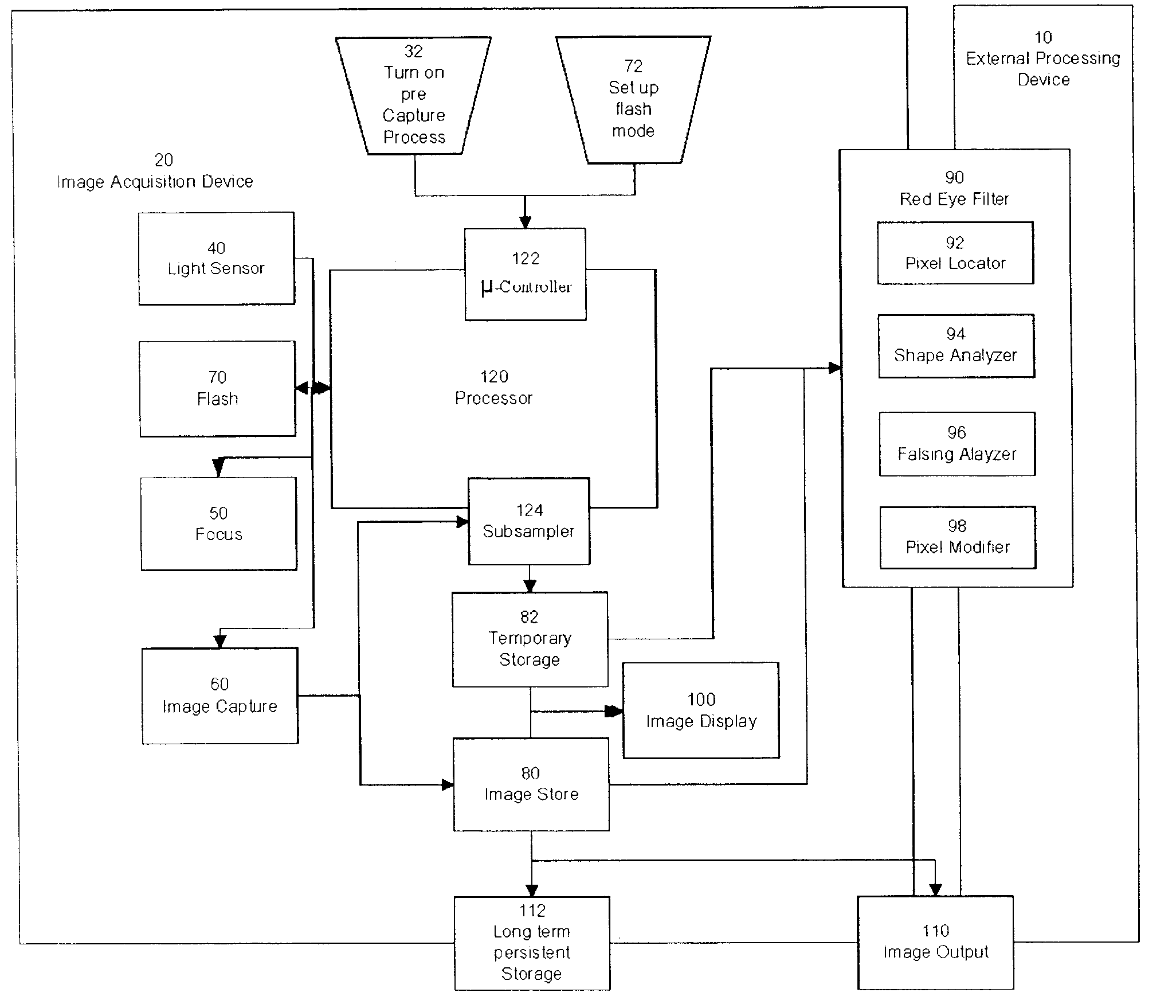
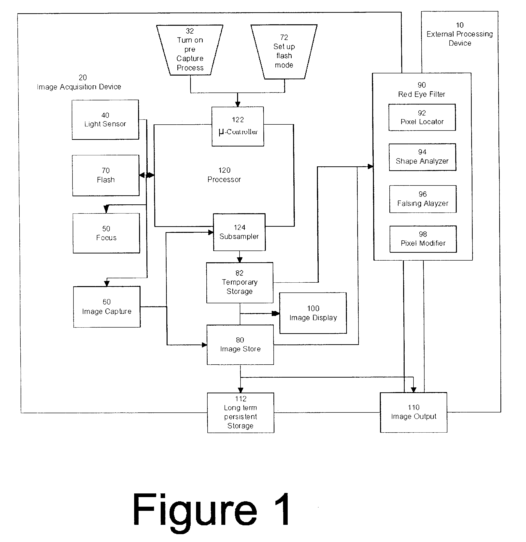
[0029]FIG. 1 shows a block diagram of a image acquisition system such as a digital camera apparatus operating in accordance with the present invention. The digital acquisition device, also generically referred to in this application as a camera 20, includes a processor 120. It can be appreciated that many of the processes implemented in the digital camera may be implemented in or controlled by software operating in a microprocessor (μProc), central processing unit (CPU), controller, digital signal processor (DSP) and / or an application specific integrated circuit (ASIC), collectively depicted as block 120 and termed as “processor”. Generically, all user interface and control of peripheral components such as buttons and display is controlled by a μ-controller 122. The processor 120, in response to a user input at 122, such as half pressing a shutter button (pre-capture mode 32), initiates and controls the digital photographic process. Ambient light exposure is determined using light s...


PUM


Abstract

A digital image acquisition system having no photographic film, such as a digital camera, has a flash unit for providing illumination during image capture and a red-eye filter for detecting a region within a captured image indicative of a red-eye phenomenon, the detection being based upon a comparison of the captured image and a reference image of nominally the same scene taken without flash. In the embodiment the reference image is a preview image of lower pixel resolution than the captured image, the filter matching the pixel resolutions of the captured and reference images by up-sampling the preview image and / or sub-sampling the captured image. The filter also aligns at least portions of the captured image and reference image prior to comparison to allow for, e.g. movement in the subject.

Description

PRIORITY AND RELATED APPLICATIONS[0001]This application is a continuation of U.S. patent application Ser. No. 10 / 919,226, filed Aug. 16, 2004, published as US2005 / 0041121, which is a continuation-in-part (CIP) application which claims the benefit of priority to U.S. patent application Ser. No. 10 / 772,767, filed Feb. 4, 2004, now U.S. Pat. No. 7,352,394 issued Apr. 1, 2008, which is a CIP that claims the benefit of priority to U.S. patent application Ser. No. 10 / 635,862, published as US2004 / 0223063 which is a CIP that claims the benefit of priority to U.S. patent application Ser. No. 10 / 170,511, filed Jun. 12, 2002, now U.S. Pat. No. 7,042,505 issued May 9, 2006, which is a continuation of U.S. patent application Ser. No. 08 / 947,603, filed Oct. 9, 1997, now U.S. Pat. No. 6,407,777, issued Jun. 18, 2002, which are each hereby incorporated by reference. This application is also related to U.S. patent applications No. 10 / 635,918, filed Aug. 5, 2003, published as US2005 / 0031224, 10 / 773,0...

Claims


Application Information

Patent Timeline
Patent Type & Authority Applications(United States)
IPC IPC(8): H04N5/217G06K9/00G06T1/00G06T5/00G06T5/50G06T7/00G06T7/40H04N1/62H04N5/235
CPCG06K9/00248H04N9/70G06T5/008G06T7/408G06T2207/10024G06T2207/30201G06T2207/30216H04N1/6086H04N1/62H04N1/624H04N5/2354G06K9/00234H04N5/23229H04N5/23293G06K9/0061G06T7/90G06V40/165G06V40/193H04N23/63H04N23/74G06V40/162H04N23/80
Inventor STEINBERG, ERANPRILUTSKY, YURYCORCORAN, PETERBIGIOI, PETRONELDELUCA, MICHAEL J.
Owner FOTONATION LTD
Why Eureka
Try Eureka