Mixing Apparatus

a technology of mixing apparatus and mixing chamber, which is applied in the direction of osteosynthesis devices, prosthesis, transportation and packaging, etc., can solve the problem that mixing may take a longer tim

Active Publication Date: 2008-09-04
DEPUY SYNTHES PROD INC
View PDF100 Cites 74 Cited by
  • Summary
  • Abstract
  • Description
  • Claims
  • Application Information

AI Technical Summary

Benefits of technology

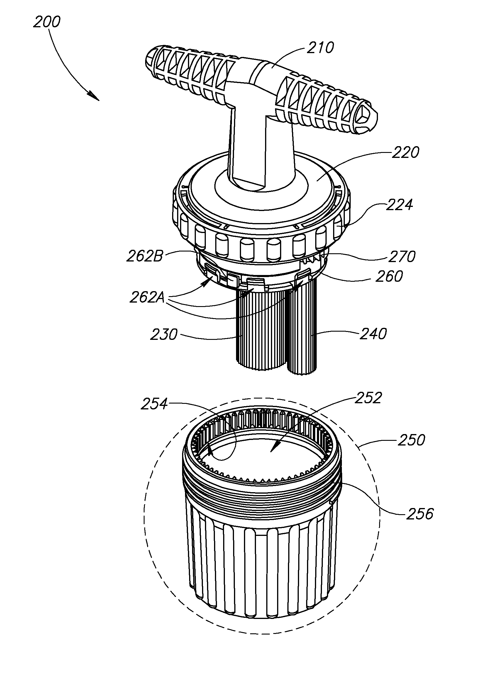
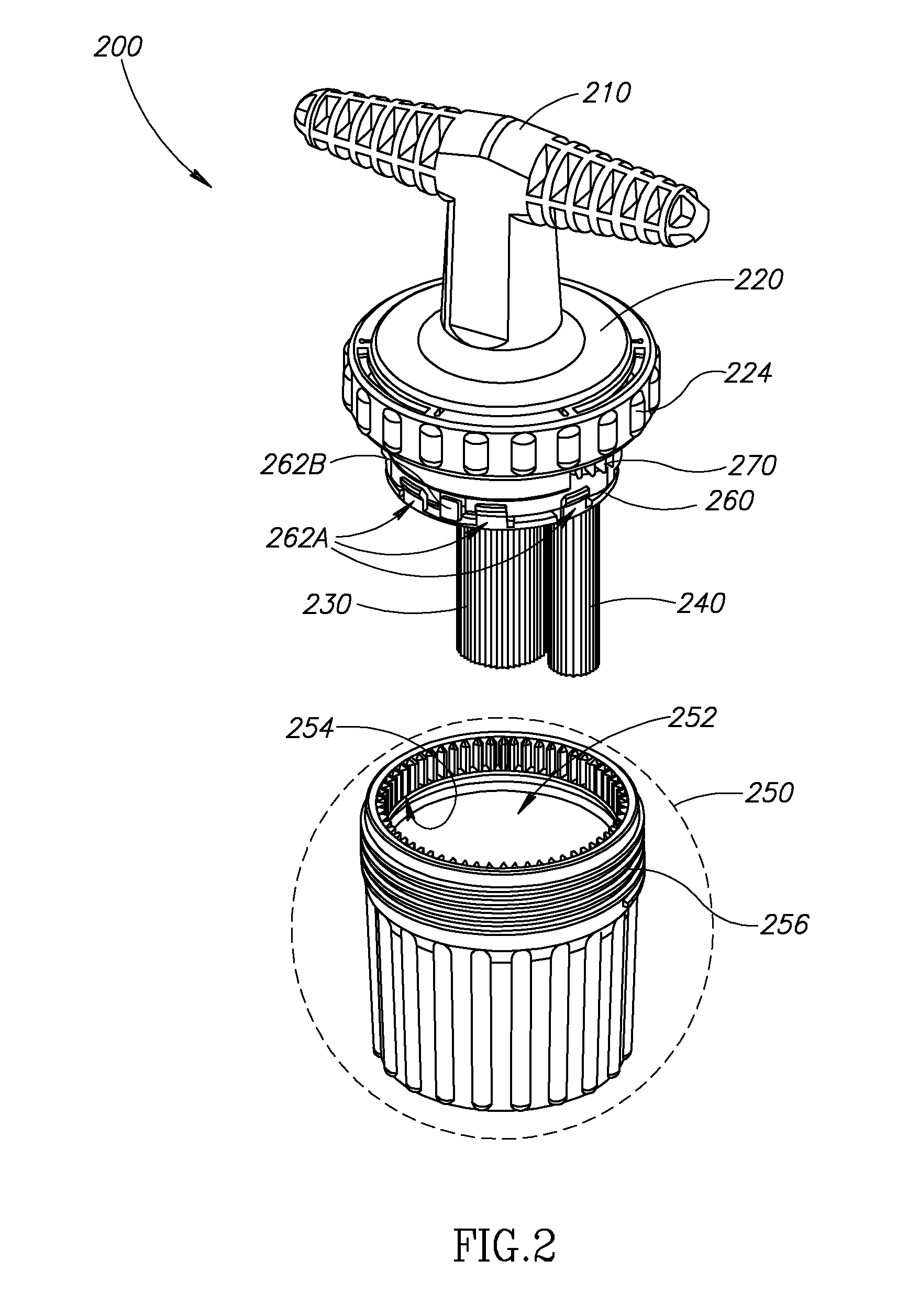
[0084]c) operating a manual drive mechanism to cause the planetary mixing element to both rotate about its own axis and revolve around the central mixing element in order to mix the components to form a mixture.

Problems solved by technology

However, under some circumstances the mixing may take a longer time.

Method used


Image

  • Mixing Apparatus
  • Mixing Apparatus
  • Mixing Apparatus

Examples


Embodiment Construction

Overview

[0110]U.S. application 60 / 738,556; U.S. 60 / 762,789; U.S. 60 / 765,484; and Ser. No. 11 / 360,251 (hereinafter “the inventor's previous applications”), the disclosures of which are each fully incorporated herein by reference, disclose polymeric bone cement formulations which are characterized by a rapid transition to a high viscosity state. According to exemplary cement formulations disclosed in these applications, mixture of monomer and polymer components produces a mixture characterized by a viscosity in the range of 400 to 500 Pascal / second substantially as soon as the polymer is wetted by the monomer. In practice, this can take as little as 30 seconds.

[0111]Previously available bone cement formulations were characterized by a relatively long liquid phase and a short working window during which the cement was suitable for injection. A new class of cement formulations, disclosed in the inventor's previous applications is characterized by a rapid transition to a high viscosity w...


PUM

PropertyMeasurementUnit
internal volumeaaaaaaaaaa
inner volumeaaaaaaaaaa
volumesaaaaaaaaaa

Abstract

A mixing apparatus comprising: a) a mixing well characterized by an internal volume not exceeding 100 ml.; b) a drive mechanism including a stationary circumferential gear on an inner surface of the mixing well; and c) a planetary mixing element driven by a mixing element gear which engages the stationary circumferential gear.

Description

RELATED APPLICATIONS[0001]The present application claims the benefit under 119(e) of U.S. provisional patent applications U.S. 60 / 738,556, filed on Nov. 22, 2005, U.S. 60 / 762,789, filed on Jan. 26, 2006; and U.S. 60 / 765,484, filed on Feb. 2, 2006 all of which are entitled “METHODS, MATERIALS AND APPARATUS FOR TREATING BONE AND OTHER TISSUE”.[0002]The present application is also a continuation in part of U.S. patent application Ser. No. 11 / 360,251 entitled “METHODS, MATERIALS AND APPARATUS FOR TREATING BONE AND OTHER TISSUE”, filed on Feb. 22, 2006.FIELD OF THE INVENTION[0003]The present invention relates to mixing apparatus and to methods of mixing.BACKGROUND OF THE INVENTION[0004]Mechanical mixers for mixing components to homogeneity are well known. Their applications include, but are not limited to, baking, building construction and medicine.[0005]Mixing apparatus for high viscosity mixtures must be adapted to provide sufficient shear force to continue moving against great resista...

Claims


Application Information

Patent Timeline
Patent Type & Authority Applications(United States)
IPC IPC(8): B01F7/30B01F25/62B01F23/57
CPCA61F2/44B01F7/305A61F2002/30523A61F2002/4685A61F2002/4693A61F2220/0025B01F7/005B01F7/00975B01F7/00991B01F7/30B01F13/002B01F13/0033B01F15/00019B01F15/00058B01F15/0279B01F2215/0029A61F2/4601Y10T137/86035B01F27/116B01F27/2322B01F27/2324B01F27/95B01F27/951B01F33/5011B01F33/5014B01F35/145B01F35/123B01F35/754251B01F2101/20A47J44/02B01F35/323B01F35/75425A61B17/8833
Inventor GLOBERMAN, ORENBEYAR, MORDECHAY
Owner DEPUY SYNTHES PROD INC
Why Eureka
Try Eureka