Working Vehicle Transmission System

a transmission system and working vehicle technology, applied in the direction of fluid gearings, road transportation, gearing, etc., can solve the problems of system failure to achieve the level of smooth acceleration and gear shifting experience, and high speed movement of a working vehicle equipped with this conventional working vehicle transmission system, etc. achieve the effect of reducing power transmission and fuel consumption, reducing workability

Inactive Publication Date: 2008-09-04
KANZAKI KOKYUKOKI MFG
View PDF6 Cites 47 Cited by
  • Summary
  • Abstract
  • Description
  • Claims
  • Application Information

AI Technical Summary

Benefits of technology

[0006]An object of the invention is to provide a working vehicle transmission system, including a multistage transmission, wherein the multistage transmission speed-changes power from a prime mover at one of various speeds so as to correspond to different conditions (such as different vehicle traveling speeds), while allowing for efficiencies in workability, power transmission and fuel consumption.

Problems solved by technology

However, a gearshift of such a multistage transmission using mechanical clutches still lacks optimal smoothness and continuity.
Especially at high speeds, this system cannot achieve the levels of smooth acceleration and gear shifting experienced in ordinary passenger cars.
As a result, when comfort and stability are considered, high speed movement of a working vehicle equipped with this conventional working vehicle transmission system is problematic.
Further, in the middle or low speed ranges, a gearshift of the multistage transmission does not precisely correspond to the ever-changing traveling speed of the vehicle, thereby hindering the workability, power transmission efficiency, and fuel efficiency of the vehicle.

Method used


Image

  • Working Vehicle Transmission System
  • Working Vehicle Transmission System
  • Working Vehicle Transmission System

Examples


first embodiment

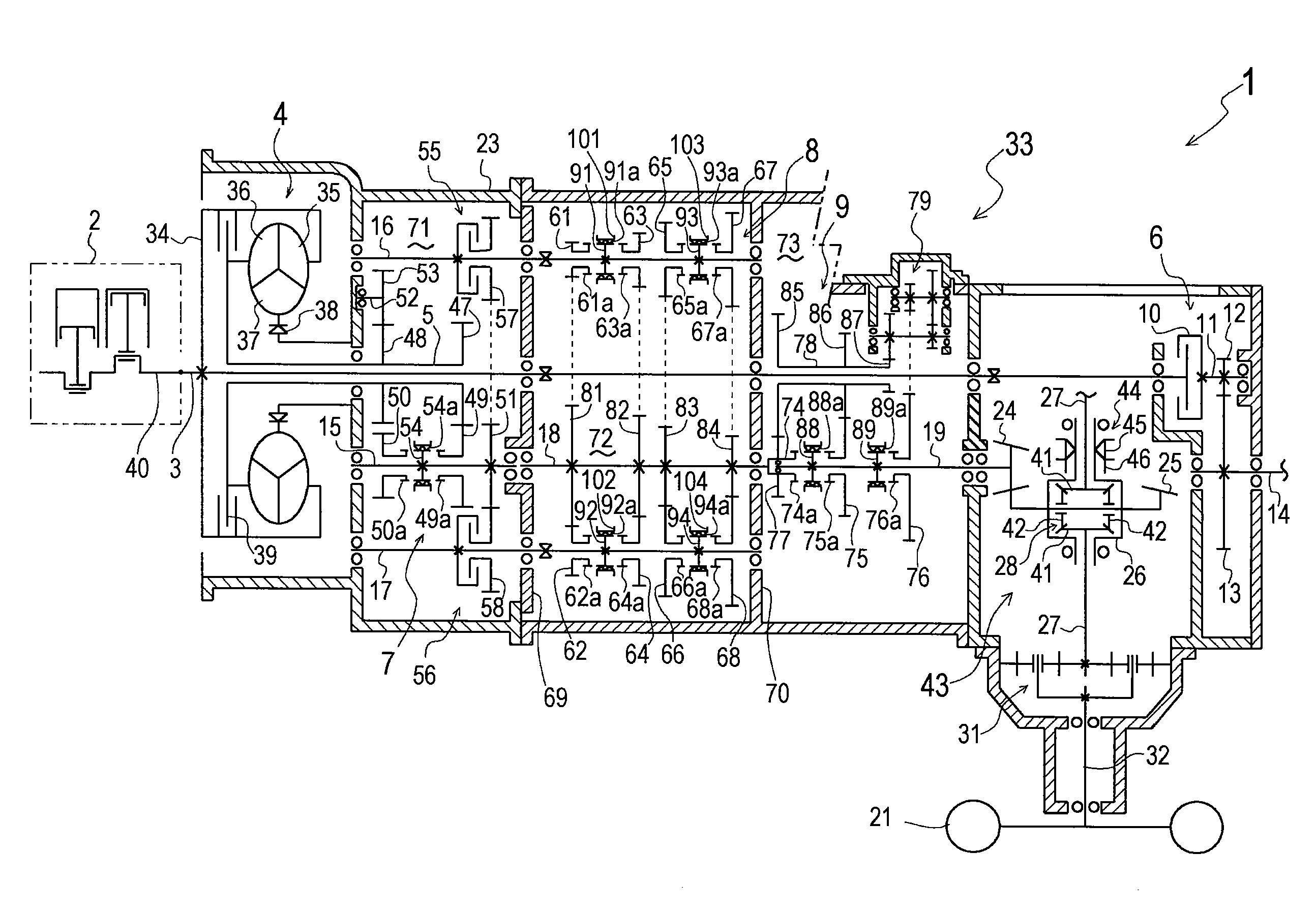
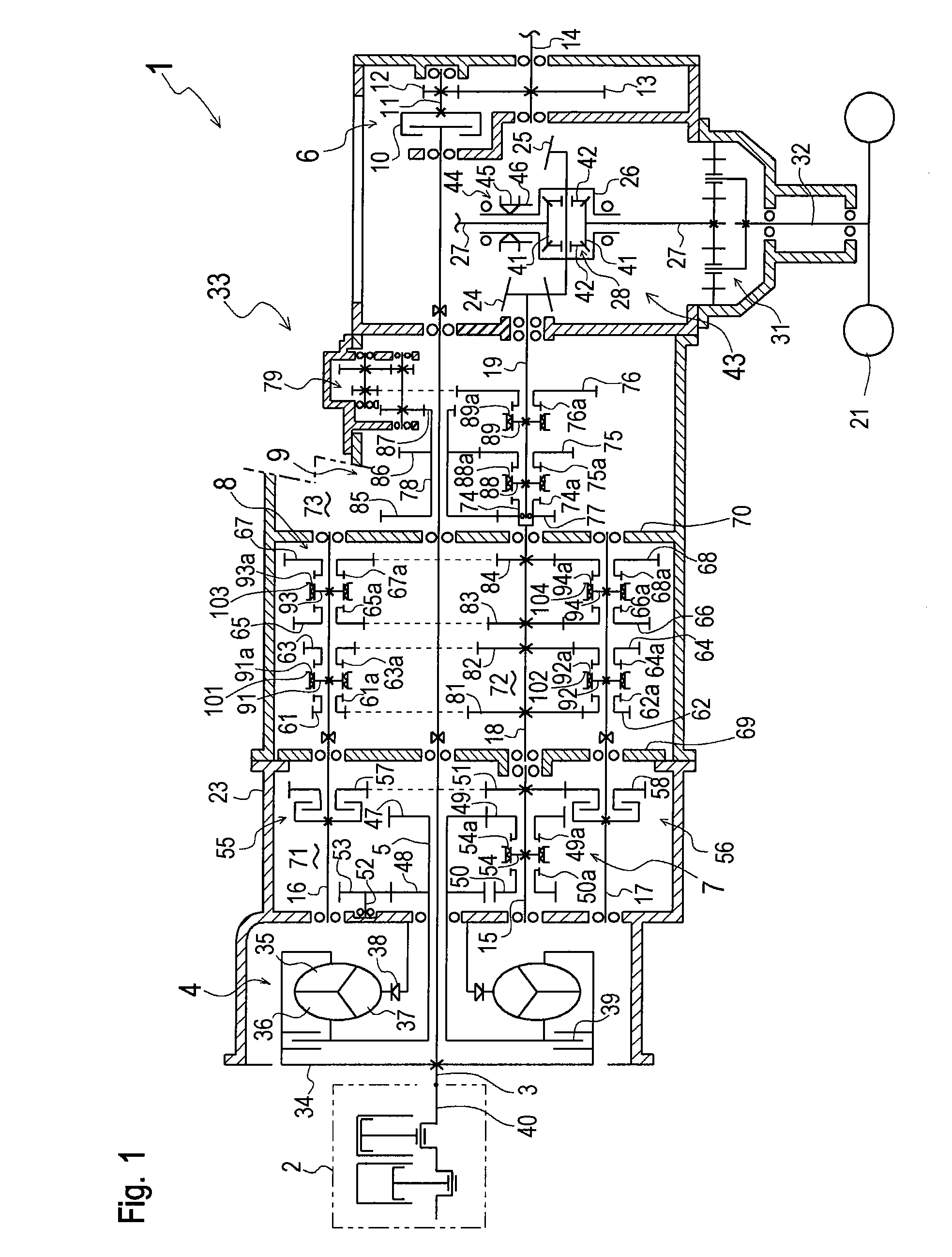
[0057]An entire construction of a working vehicle transmission system 1 will be described with reference to FIG. 1. Especially, working vehicle transmission system 1 is adapted to a four-wheel drive agricultural tractor equipped with a prime mover 2, such as an engine or an electric motor, and includes a gear transmission 33 for speed-changing the rotary power stepwise from prime mover 2 (hereinafter, this rotary power is referred to as “prime mover power”).

[0058]Gear transmission 33 serving as a multistage transmission is disposed in a transmission casing 23, and includes a main input shaft 3 projecting outward from transmission casing 23 to be drivingly connected to an output shaft (or if prime mover 2 is an engine, a crankshaft) 40 of prime mover 2. In gear transmission 33, a cylindrical reverser input shaft (or a torque converter output shaft) 5 is relatively rotatably fitted on main input shaft 3. A lock-up control torque converter 4 (which can be locked up) is interposed betw...

second embodiment

[0143]In working vehicle transmission system 201 of the second embodiment, the PTO device (i.e., PTO clutch 10, PTO deceleration gear train 6 and PTO shaft 14) is connected to main input shaft 203 through torque converter 204. Therefore, in the working traveling mode with torque converter 204 which is locked up, the rotation of PTO shaft 14 is rigidly synchronous to the rotation of output shaft 40 of prime mover 2, so that PTO shaft 14 is rotated at a constant speed as long as the rotary speed of prime mover 2 is constant. On the other hand, in the non-working traveling mode with torque converter 204 which is not locked up, the rotary speed of PTO shaft 14 varies due to the variable torque function of torque converter 204. In other words, in the non-working traveling mode of working vehicle transmission system 201, the rotary speed of PTO shaft 14 automatically varies according to the traveling speed of the vehicle. Therefore, the non-working traveling mode is adapted to less intens...

third embodiment

[0152]An entire structure of working vehicle transmission system 501 will be described with reference to FIG. 12. Working vehicle transmission system 501 is adaptable to four-wheel drive working vehicles such as agricultural tractors, and is provided with a traveling speed-change mechanism 520 which speed-changes prime mover power from a prime mover 502 such as an engine or an electronic motor. Main input shaft 516 is connected to an output shaft 513 of prime mover 502, and is connected to reverser / PTO input shaft 517 through rotary damper 514. Rotary damper 514 reduces vibration of prime mover 502 transmitted to main input shaft 516, and transmits power to reverser / PTO input shaft 517, i.e., converts the output power of prime mover 502 having unsteady torque into a flat prime mover power.

[0153]Reverser / PTO input shaft 517 also serves as a pump shaft of a charge pump 515 for supplying operating fluid into a hydraulic circuit of a later-discussed hydrostatic stepless transmission (h...


PUM


Abstract

A working vehicle transmission system comprises a PTO device for driving an external working device by power of a prime mover, and a multistage transmission for transmitting power from the prime mover to an axle. The multistage transmission includes a main speed-change mechanism and a sub speed-change mechanism. The main speed-change mechanism has plural drive trains for setting respective different speed stages. The sub speed-change mechanism is disposed downstream of the main speed-change mechanism and has plural drive trains for setting respective different speed stages. The main speed-change mechanism includes a first clutch and a second clutch. The main speed-change mechanism drive trains used for setting odd-numbered speed stages are activated by engaging the first clutch. On the other hand, the main speed-change mechanism drive trains used for setting even-numbered speed stages are activated by engaging the second clutch. During a speed-change operation of the main speed-change mechanism, an engagement action of one of the first and second clutches and a disengagement action of the other of the first and second clutches overlap each other. A reverser is disposed upstream of the first and second clutches of the main speed-change mechanism so as to enable switching the direction of output rotation transmitted to the first and second clutches from one direction to the opposite direction.

Description

BACKGROUND OF THE INVENTION[0001]1. Field of the Invention[0002]The present invention relates to a working vehicle transmission system for working vehicles such as tractors, including a power take off (hereinafter referred to as a “PTO”) device for driving an external working device by a prime mover, and a multistage transmission for transmitting power from the prime mover to an axle.[0003]2. Related Art[0004]As disclosed in JP 2003-314679A, there is a well-known working vehicle transmission system used for working vehicles such as tractors, in which a multistage transmission includes two mechanical clutches such that, during a gearshift, the engaging action of one clutch overlaps the disengaging action of the other clutch so as to create a double clutch-engaging state. This permits gear shifting without interrupting the transmission of rotary power from a prime mover, such as an engine or an electric motor, to an axle.[0005]This double clutch action somewhat reduces shocks generate...

Claims


Application Information

Patent Timeline
Patent Type & Authority Applications(United States)
IPC IPC(8): F16H47/04
CPCB60K17/28F16H3/006F16H3/14F16H37/043F16H47/02Y02T10/76F16H47/06F16H2003/0822F16H2037/044F16H2037/049F16H2037/0886F16H47/04
Inventor HASEGAWA, TOSHIYUKIEBIHARA, TOMOYUKIISHII, NORIHIROKOGA, KAZUNARI
Owner KANZAKI KOKYUKOKI MFG
Why Eureka
Try Eureka