Esophageal Electrocatheter

Active Publication Date: 2008-09-04
FIAB
View PDF16 Cites 18 Cited by
  • Summary
  • Abstract
  • Description
  • Claims
  • Application Information

AI Technical Summary

Benefits of technology

[0007]This invention therefore has for an aim to provide a device that overcomes the drawbacks of prior art in

Problems solved by technology

It is also known that in some circumstances, repeated and excessive heating of the tissue concerned causes swellings which, over time, may lead to necrosis putting the patient's health at serious risk.
These tech

Method used


Image

  • Esophageal Electrocatheter
  • Esophageal Electrocatheter

Examples


Embodiment Construction

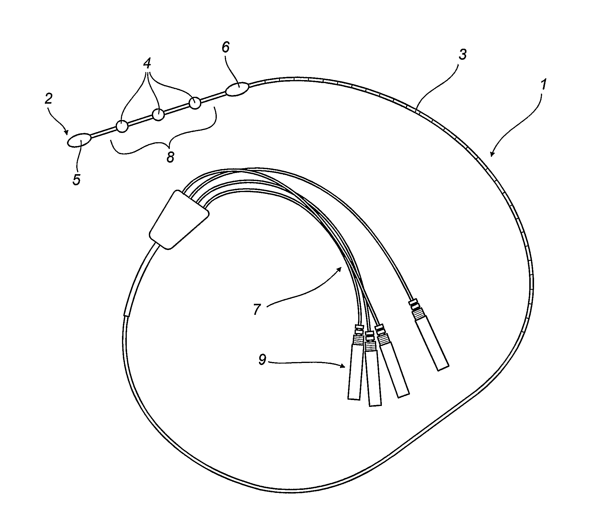
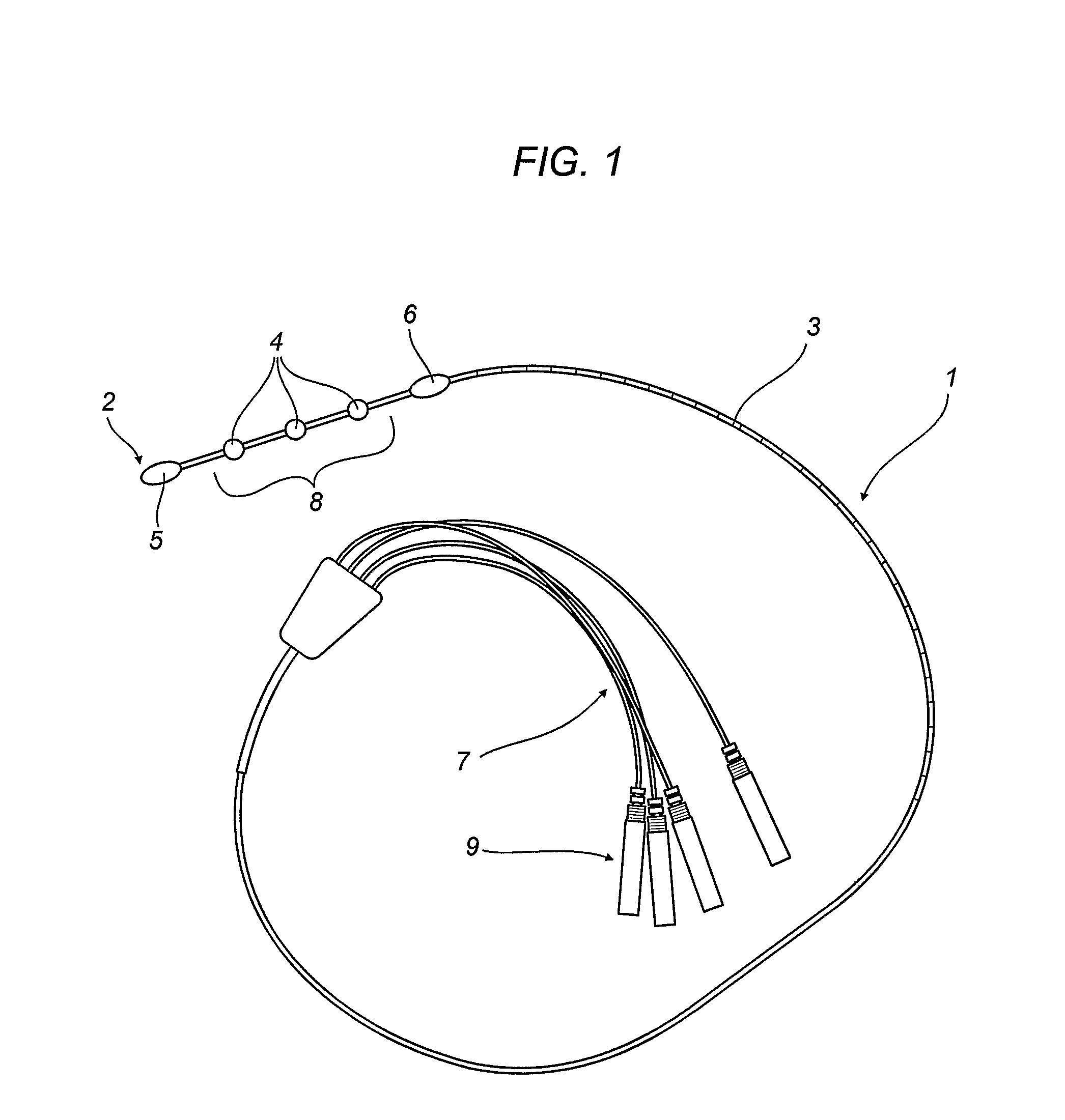
[0012]With reference to the accompanying drawing, a catheter according to the invention comprises a flexible insertion element 1, including a sheath 3 that terminates with a distal end 2.

[0013]In the vicinity of or at the distal end 2, there are reference elements 5, 6 which define a zone 8 where the temperature may be detected and / or monitored by one or more temperature sensors 4.

[0014]In the embodiment described, there are three temperature sensors 4 which can detect a central value and the deviation from this value at two symmetrical, equidistant points.

[0015]Preferably, the sensors consist of thermocouples whose connecting cables 7 run inside the sheath 3 and terminate outside it with connectors 9 for connection to an external control unit that is not shown in the drawing.

[0016]Also preferably, the elements 5, 6 consist of X-ray traceable parts enabling the monitoring zone 8 to be positioned along the esophagus after insertion of the catheter according to radiological practice.

[...


PUM


Abstract

An esophageal catheter comprises an insertion element (1) able to be inserted into a patient's esophagus and having a distal end (2) and a sheath (3) containing the cables (7) for connection to at least two temperature sensors (4) fitted along the element (1) in the vicinity of the distal end, the sensors being mounted in predetermined positions relative to one or more positioning elements (5, 6) defining a temperature detection zone (8).

Description

TECHNICAL FIELD[0001]This invention relates to an esophageal electrocatheter for use in cardiac ablation operations.BACKGROUND ART[0002]It is known that some disorders, such as atrial fibrillation in particular, are treated by ablation techniques whereby radio frequency irradiations are applied to the heart tissue (in particular to the atrial walls) in order to restore normal functioning of the electrical conduction of the heart and reduce the occurrence of fibrillation.[0003]These techniques therefore use a source of radio frequency energy which, besides performing the function just mentioned, involve heating the offending tissue and the tissue of the surrounding areas.[0004]It is also known that in some circumstances, repeated and excessive heating of the tissue concerned causes swellings which, over time, may lead to necrosis putting the patient's health at serious risk.[0005]At present, the heating level reached during cardiac ablation operations is controlled with the aid of co...

Claims


Application Information

Patent Timeline
IPC IPC(8): A61B18/14
CPCA61B5/0008A61B5/01A61B5/4233A61B5/6852A61B2018/00797A61B19/54A61B2017/00101A61B2017/00119A61B2018/00351A61B18/1206A61B90/39
Inventor CALABRO, ALBERTODEL BENE, PASQUALE
Owner FIAB
Why Eureka
Try Eureka