

Intraoperative Membrane Cutting Tool
a cutting tool and membrane technology, applied in the field of intraoperative membrane cutting tools, can solve the problems of increasing the amount of time and effort spent on shaping the membrane, affecting the sterility of the sample,
- Summary
- Abstract
- Description
- Claims
- Application Information
AI Technical Summary
Problems solved by technology
Method used
Image

Examples
second embodiment
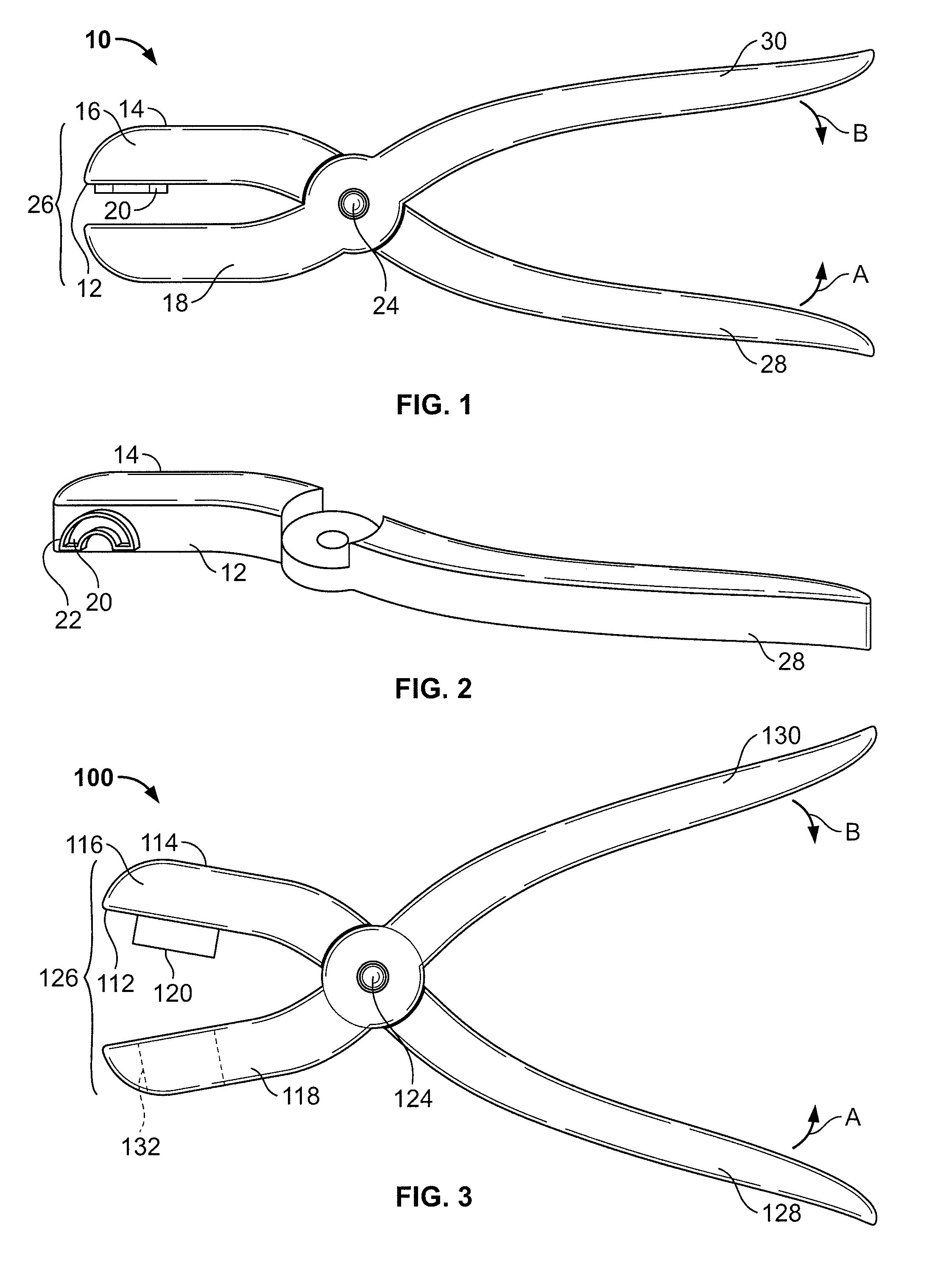
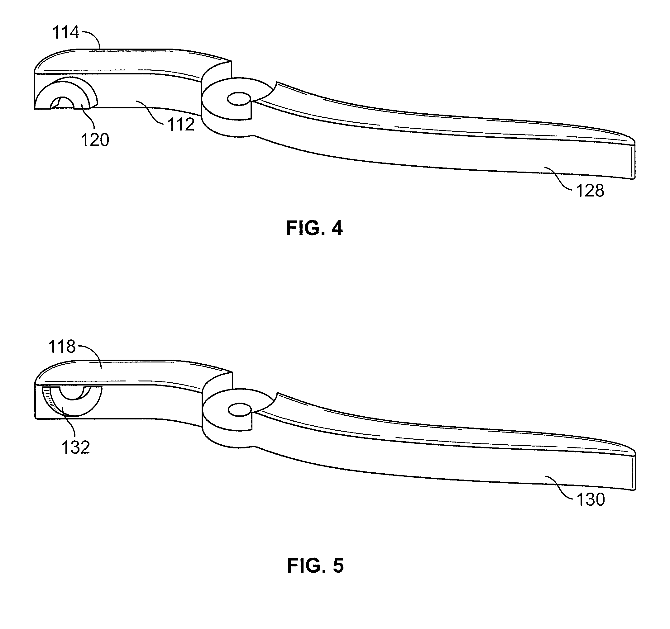
[0031]In FIGS. 3-5 there is illustrated a cutting tool 100. The cutting tool 100 includes a jaw 126 defined by a cutting portion 116 and an anvil portion 118. A first handle 128 and a second handle 130 are attached to each of the jaw portions 116 and 118, respectively, and the handles 128 and 130 are used to open and close the jaw 126. The cutting portion 116 includes a punch 120 having a shape and size of a desired membrane piece. The anvil portion 118 includes a receiving aperture 132 sized and shaped to correspond to that of the punch to receive at least a portion of the punch 120 during cutting operations. To cut a desired membrane shape, a membrane sheet is placed in between the jaw 126 when opened, and the handles 128 and 130 are then squeezed to close the jaw 126, causing the punch 120 to come into contact with the membrane sheet and to cut the membrane in the desired shape and size. More specifically, the punch 120 passes into the receiving aperture 132, where the membrane i...
first embodiment
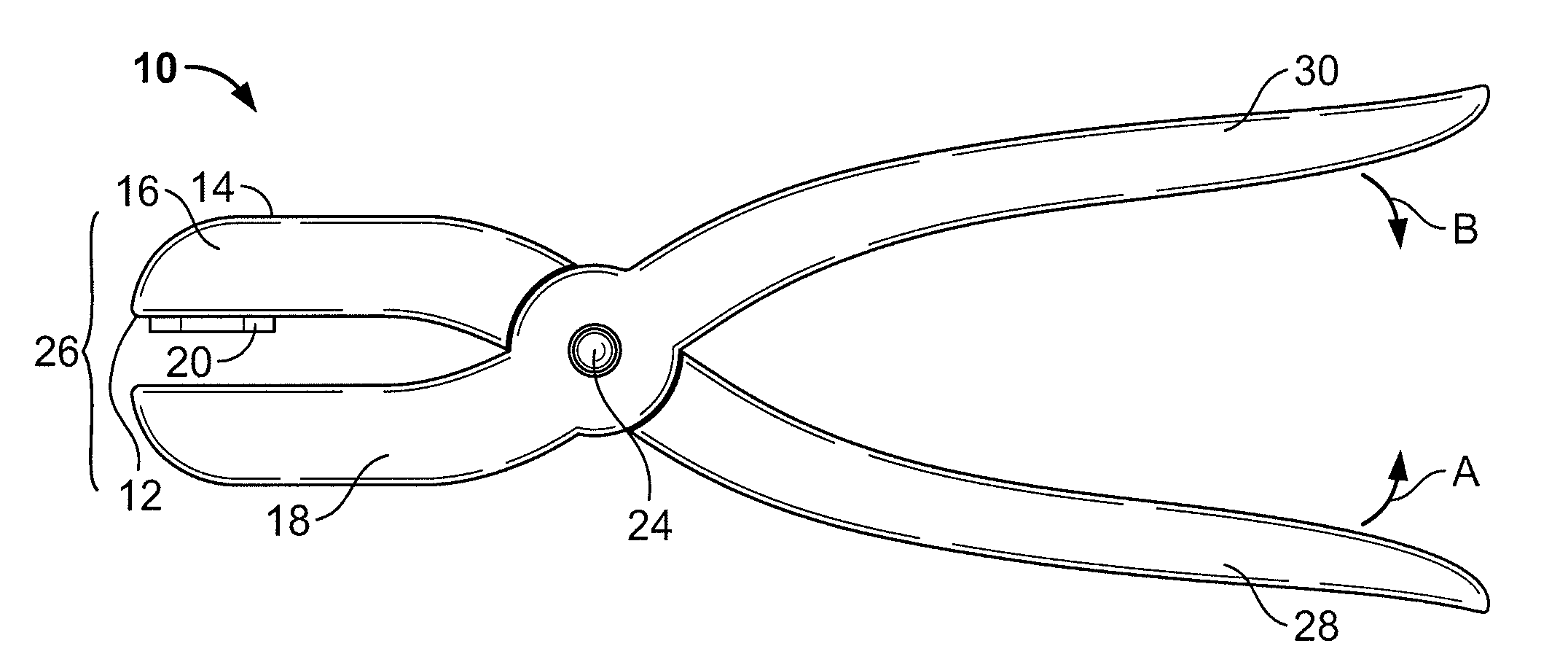
[0035]The anvil portion 118 opposes the cutter body 116 and provides a support surface upon which the tissue membrane can rest on during cutting operations. The anvil portion 118 defines the receiving aperture 132. The anvil portion 118 communicates with the second handle 130 and the cutter body 116 communicates with a first handle 128, where both handles are connected to each other at a common pivot point 124. Preferably, the first handle 128 extends from the cutter body 116, and the second handle 130 extends from the anvil portion 118. The two handles 128 and 130 are brought towards one another as designated by arrows A and B in FIG. 3. As the handles 128 and 130 are moved toward one another, the cutter body 116 and the anvil portion 118 similarly move towards one another. As the cutter body 116 and the anvil portion 118 are brought together, the punch 120 is pressed against the sheet of tissue membrane and subsequently passes into the receiving aperture 132. The shearing force on...
third embodiment
[0037]In FIGS. 6 and 7 there is illustrated a cutting tool 200 having a jaw 226 defined by a plurality of cutters 216 and an anvil 218 generally opposing the cutters 216. A dial 234, or selector plate, includes the cutters 216, each having a knife edge 222 with a perimeter shaped to resemble the size and shape of a different desired tissue membrane piece. A first handle 228 and a second handle 230 operate the jaw portions 216 and 218, respectively, between an open and cutting position. To cut a membrane piece, the size and / or shape is first selected by rotating the dial 234 to shift the desired knife edge 222 into cutting position over the anvil 218. The membrane sheet is placed in the jaw 226 when opened and the handles 228 and 230 are then squeezed to close the jaw 226, causing the knife edge 222 selected on the dial portion 234 to come into contact with the membrane sheet and to cut through the membrane to the anvil 218.
[0038]The cutters 216 of the dial 234 each have a different ...
PUM
 Abstract
Description
Claims
Application Information