
Design structure for task based debugger (transaction-event -job-trigger)

a task and debugger technology, applied in the field of task based debuggers, can solve the problems of difficult simulation of the entire functional scope of an soc implementation, the complexity and size of soc chips outpacing the growth of simulation technologies, and the meaningless trace data inside the core of the system engineer's mind

Inactive Publication Date: 2008-09-04
IBM CORP
View PDF4 Cites 11 Cited by
  • Summary
  • Abstract
  • Description
  • Claims
  • Application Information

AI Technical Summary

Benefits of technology

The invention provides a design structure for a task-based debugger for a system-on-chip (SOC). It includes a controller that captures system events from functional cores in the SOC and identifies bug events. The controller can turn on or off recording of different types of system events and sends the events to a table for analysis. The invention also provides a method for monitoring events on the SOC and generating a history of events for analysis. Overall, the invention improves the efficiency and accuracy of debugging and analysis of SOC systems.

Problems solved by technology

Trace data from inside of the core is often meaningless to the system-level engineer.
The growth in complexity and size of SOC chips is outstripping the growth in simulation technologies.
It is very difficult to simulate the entire functional scope of an SOC implementation, and IC's are manufactured without complete verification.
This is difficult, as it would necessitate too great of storage for all of that information, or require too great of off-chip bandwidth to move the information.
However, these methods and devices do not provide any sort of history to indicate how the chip arrived in the current state.

Method used


Image

  • Design structure for task based debugger (transaction-event -job-trigger)
  • Design structure for task based debugger (transaction-event -job-trigger)
  • Design structure for task based debugger (transaction-event -job-trigger)

Examples


Embodiment Construction

[0023]The embodiments of the invention and the various features and advantageous details thereof are explained more fully with reference to the non-limiting embodiments that are illustrated in the accompanying drawings and detailed in the following description. It should be noted that the features illustrated in the drawings are not necessarily drawn to scale. Descriptions of well-known components and processing techniques are omitted so as to not unnecessarily obscure the embodiments of the invention. The examples used herein are intended merely to facilitate an understanding of ways in which the embodiments of the invention may be practiced and to further enable those of skill in the art to practice the embodiments of the invention. Accordingly, the examples should not be construed as limiting the scope of the embodiments of the invention.

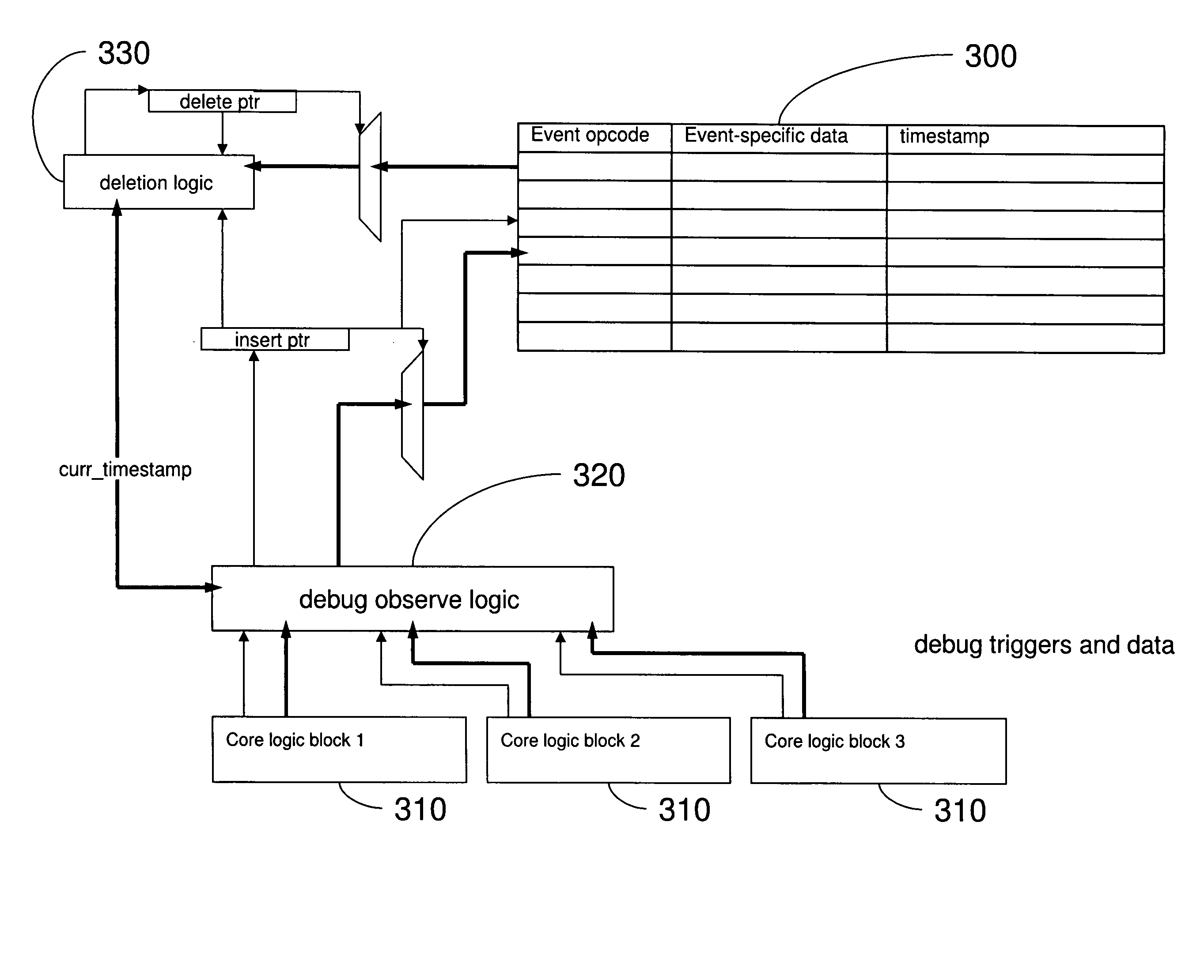
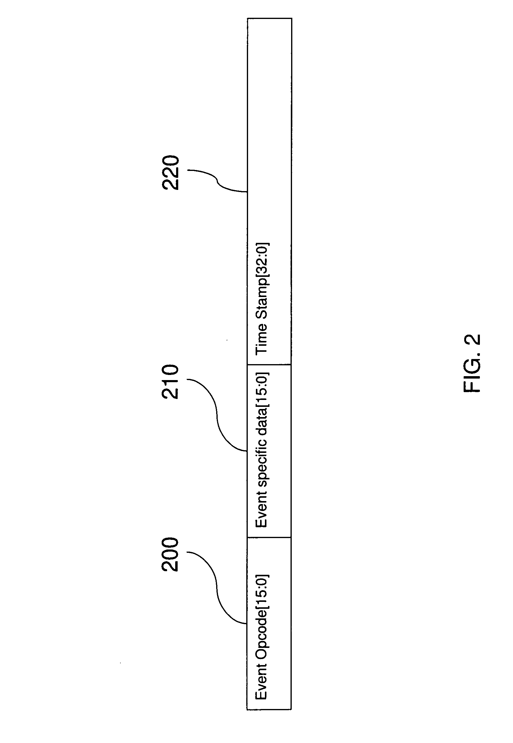
[0024]The embodiments of the invention describe an architecture for a debug system that categorizes and stores various function-specific events ...


PUM


Abstract

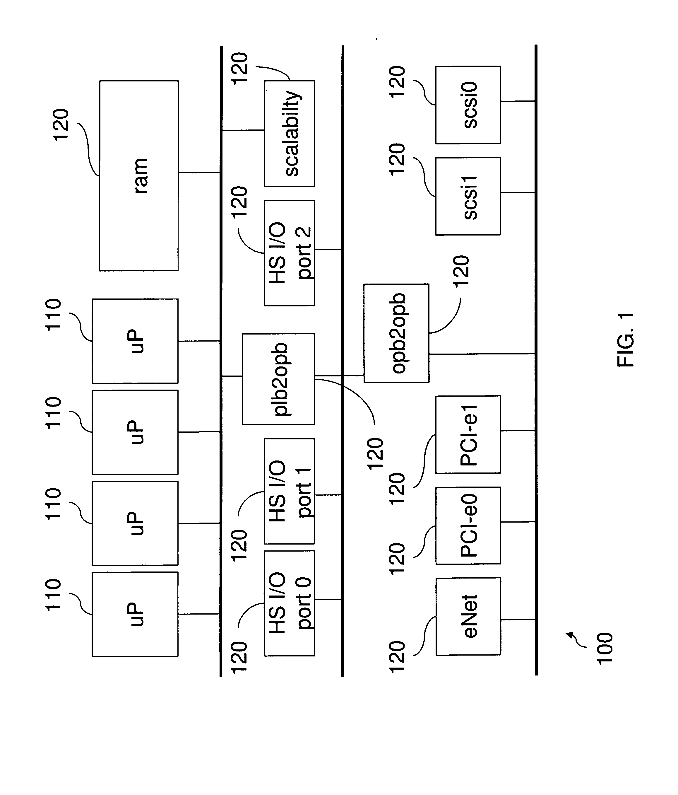
Disclosed is a design structure for an apparatus for a task based debugger (transaction-event-job-trigger). More specifically, an integrated event monitor for a SOC comprises functional cores each having a functional debug logic element. The cores are connected to an interconnect structure that links the functional debug logic elements. Each functional debug logic element is specifically dedicated to a function of its corresponding core, wherein the functional debug logic elements generate a table of function-specific system events. The system events are function-specific with respect to an associated core, wherein the system events include transaction events, controller events, processor events, interconnect structure arbiter events, interconnect interface core events, high speed serial link core events, and / or codec events.

Description

CROSS-REFERENCE TO RELATED APPLICATIONS[0001]This application is a Continuation-In-Part of U.S. application Ser. No. 11 / 461,793 filed Aug. 2, 2006, the complete disclosure of which, in its entirety, is herein incorporated by reference.BACKGROUND[0002]1. Field of the Invention[0003]The embodiments of the invention provide a design structure for an apparatus, method, etc. for a task based debugger (transaction-event-job-trigger).[0004]2. Description of the Related Art[0005]As system-on-a-chip (SOC) based integrated circuit (IC) design increases in functional capacity and complexity, the need for effective system level debug increases proportionally. Many IC design methodologies assume complete verification of subcomponents used (processors, bridges / switches, endpoint cores, and memories). While complete verification of comprising subcomponents may exist for any given SOC, this does not directly imply the completeness of verification of the complete system. Often what remains to be ver...

Claims


Application Information

Patent Timeline
Patent Type & Authority Applications(United States)
IPC IPC(8): G06F11/30
CPCG06F2217/14G06F17/5022G06F30/33G06F30/333
Inventor BUETI, SERAFINOGOODNOW, KENNETH J.LEONARD, TODD E.MANN, GREGORY J.WOODRUFF, CHARLES S.
Owner IBM CORP
Learn More