Mobile floor-cleaning machine

Inactive Publication Date: 2008-09-11
ALFRED KARCHER GMBH & CO KG
View PDF6 Cites 31 Cited by
  • Summary
  • Abstract
  • Description
  • Claims
  • Application Information

AI Technical Summary

Benefits of technology

[0024]As already mentioned, provision may be made for the carrier part to have an annular receiving space into which the tool holder enters by way of a sleeve. It is suitable here for ribs of the carrier part to protrude into the receiving space in the radial direction and corresponding ribs to project away from the sleeve of the tool holder in the radial direction. As an alternative, a reversed arrangement can also be used in such a way that the tool holder has the annular receiving space into which the carrier part enters by way of a sleeve, ribs of the tool holder protruding into the receiving space in the radial direction and corresponding ribs of the carrier part projecting away from the sleeve in the radial direction. In an embodiment of this type, the tooth system, which can be produced by means of the ribs, between the carrier part and the tool holder is disposed within a receiving space and as a result is protected against contamination and mechanical damage.
[0025]In a particularly preferred configuration of the mobile floor-cleaning machine, the carrier part comprises an outer ring and an inner ring which is aligned coaxially with said outer ring, which inner ring and outer ring between them define the receiving space for a sleeve of the tool holder, ribs which are integrally formed on the outer ring protruding into the receiving space and the inner ring being integrally connected to the outer ring by means of a plurality of cross-pieces which run in the radial direction and having a plurality of axially aligned slots, a latching hook which is integral

Problems solved by technology

The cleaning tool gradually wears down due to contact with the floor s

Method used


Image

  • Mobile floor-cleaning machine
  • Mobile floor-cleaning machine
  • Mobile floor-cleaning machine

Examples


Example

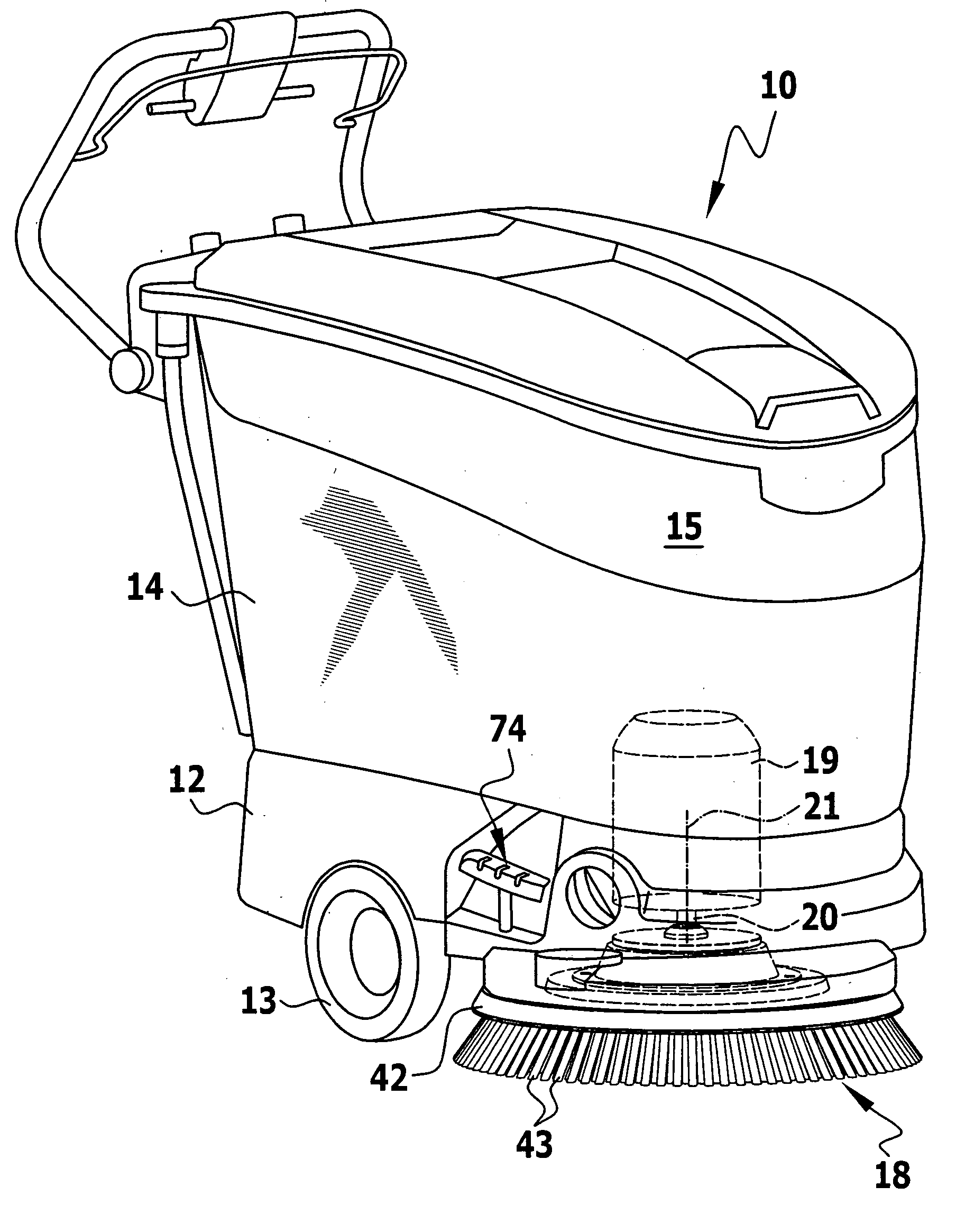
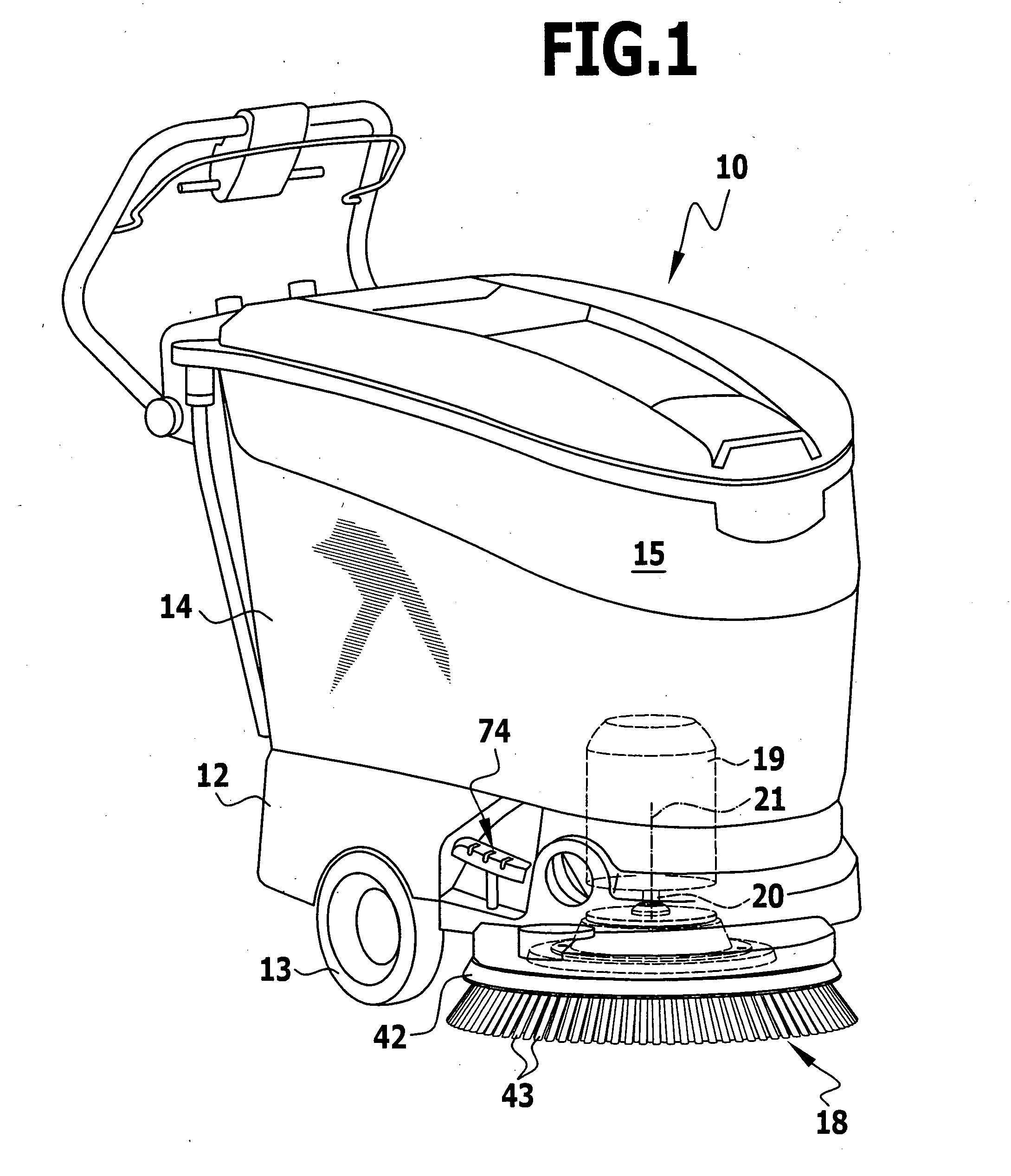
[0036]FIG. 1 schematically illustrates a mobile floor-cleaning machine according to the invention in the form of a scrubber dryer 10 with a chassis 12 on which a steerable front wheel is held and two rear wheels are held such that they can rotate about a common rotation axis, only a rear wheel 13 being visible in the drawing. The chassis carries a reservoir 14 for cleaning liquid and a receptacle 15 for soiled cleaning liquid which protrudes into the top of the reservoir 14.

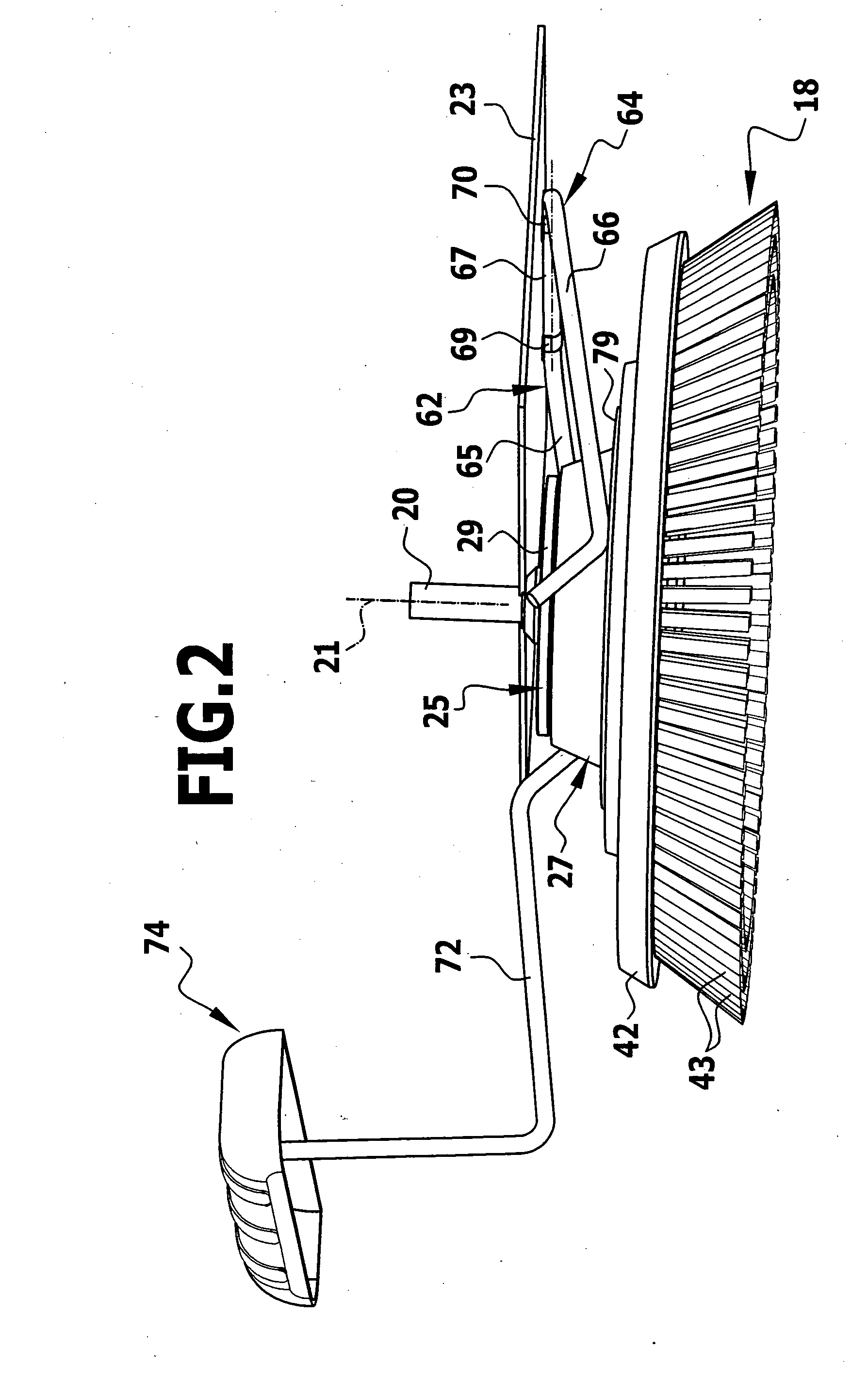
[0037]Disposed beneath the chassis 12 is disk-like cleaning tool in the form of a plate brush 18, which brush can be rotationally driven by a drive motor 19 via a drive shaft 20 about a rotation axis 21 of the drive shaft is. As is clear in particular from FIGS. 2 and 3, the drive shaft 20 passes through a base plate 23 of the scrubber dryer 10 and carries, at its free end, a tool holder 25 with which a carrier part 27 of the plate brush 18 can be made to engage. The structure of the tool holder 25 and of the car...


PUM


Abstract

The invention relates to a mobile floor-cleaning machine having a rotationally drivable, disk-like cleaning tool which is detachably held on a tool holder, the tool holder being connected to a drive shaft in a rotationally fixed manner. In order to develop the floor-cleaning machine in such a way that the cleaning tool can be easily replaced, the invention proposes that said cleaning tool is adapted to be detachably latched to the tool holder and to be disconnected from the tool holder in the axial direction by means of an unlatching mechanism which is adapted to be operated by the user.

Description

[0001]This application is a continuation of international application number PCT / EP2006 / 007194 filed on Jul. 21, 2006.[0002]The present disclosure relates to the subject matter disclosed in international application number PCT / EP2006 / 007194 of Jul. 21, 2006 and German application number 10 2005 045 310.4 of Sep. 16, 2005, which are incorporated herein by reference in their entirety and for all purposes.BACKGROUND OF THE INVENTION[0003]The invention relates to a mobile floor-cleaning machine having a rotationally drivable, disk-like cleaning tool which is detachably held on a tool holder, the tool holder being connected to a drive shaft in a rotationally fixed manner.[0004]Floor-cleaning machines of this type are used, for example, in the form of so-called scrubber dryers in which the cleaning tool is in the form of a disk brush which slides along the floor and to which cleaning liquid, preferably water, is supplied. Downstream of the floor-cleaning machine, the cleaning liquid which...

Claims


Application Information

Patent Timeline
IPC IPC(8): A47L11/00A47L11/02A46B13/00
CPCA47L11/4052A47L11/40A47L11/283A47L11/4038
Inventor WALZ, JUERGENWELLER, UWEKRAL, ANDREASSCHNEIDER, DIETMARSCHICK, ROLAND
Owner ALFRED KARCHER GMBH & CO KG
Why Eureka
Try Eureka